

Question: This is our lab for tomorrow and I don't know how to do it. Can u please draw a circuit with ground and power and
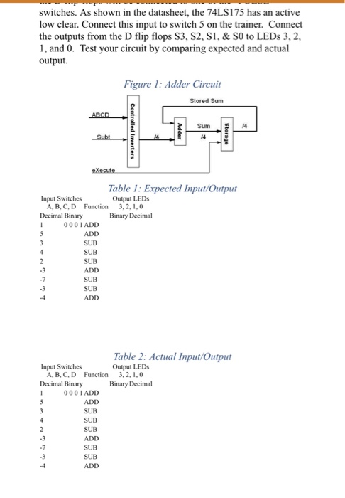
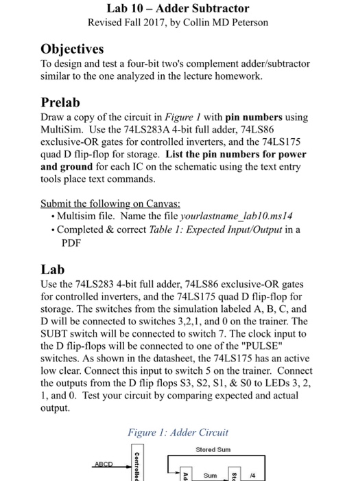
switches. As shown in the datasheet, the 74LS175 has an active low clear. Connect this input to switch 5 on the trainer. Connect the outputs from the D flip flops S3, S2, S, & SO to LEDs 3, 2, 1, and 0. Test your circuit by comparing expected and actual output Figure 1: Adder Circuit Stored Sum Sum 4 Table 1: Expected Input/Output Output LEDs Input Switches A, B, C, D Function Decimal Binary 3,2, 1,0 Binary Decimal 0001 ADD ADD SUB SUB SUB Table 2: Actual Input/Output Input Switches Output LEDs 3,2, 1.0 A, B, C, D Function Decimal Binary Binary Decimal 000 1 ADD SUB SUB SUB ADD SUB SUB switches. As shown in the datasheet, the 74LS175 has an active low clear. Connect this input to switch 5 on the trainer. Connect the outputs from the D flip flops S3, S2, S, & SO to LEDs 3, 2, 1, and 0. Test your circuit by comparing expected and actual output Figure 1: Adder Circuit Stored Sum Sum 4 Table 1: Expected Input/Output Output LEDs Input Switches A, B, C, D Function Decimal Binary 3,2, 1,0 Binary Decimal 0001 ADD ADD SUB SUB SUB Table 2: Actual Input/Output Input Switches Output LEDs 3,2, 1.0 A, B, C, D Function Decimal Binary Binary Decimal 000 1 ADD SUB SUB SUB ADD SUB SUB
Step by Step Solution
There are 3 Steps involved in it

Get step-by-step solutions from verified subject matter experts