Answered step by step
Verified Expert Solution
Question
1 Approved Answer
To accomplish this, you shall create a 4-1 MUX in LogicWorks. You wil create the 4-1 MUX using inverters and tri-state buffers. Procedure: 1. The
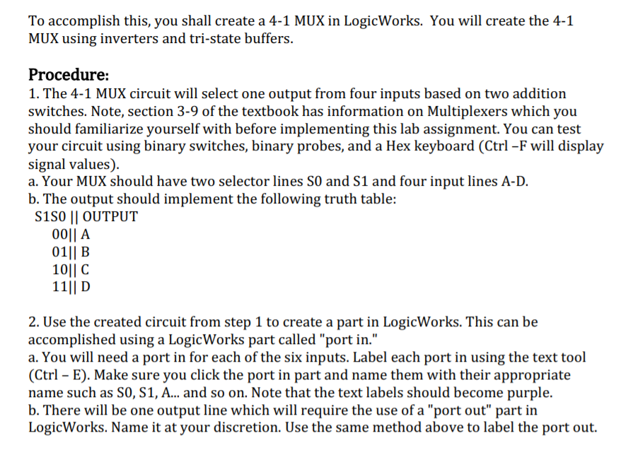
To accomplish this, you shall create a 4-1 MUX in LogicWorks. You wil create the 4-1 MUX using inverters and tri-state buffers. Procedure: 1. The 4-1 MUX circuit will select one output from four inputs based on two addition switches. Note, section 3-9 of the textbook has information on Multiplexers which you should familiarize yourself with before implementing this lab assignment. You can test your circuit using binary switches, binary probes, and a Hex keyboard (Ctrl -F will display signal values) a. Your MUX should have two selector lines SO and S1 and four input lines A-D. b. The output should implement the following truth table: S1S0 II OUTPUT 001l A 01 B 1011 C 11 D 2. Use the created circuit from step 1 to create a part in LogicWorks. This can be accomplished using a LogicWorks part called "port in." a. You will need a port in for each of the six inputs. Label each port in using the text tool (Ctrl E). Make sure you click the port in part and name them with their appropriate name such as SO, S1, A... and so on. Note that the text labels should become purple. b. There will be one output line which will require the use of a "port out" part in LogicWorks. Name it at your discretion. Use the same method above to label the port out. To accomplish this, you shall create a 4-1 MUX in LogicWorks. You wil create the 4-1 MUX using inverters and tri-state buffers. Procedure: 1. The 4-1 MUX circuit will select one output from four inputs based on two addition switches. Note, section 3-9 of the textbook has information on Multiplexers which you should familiarize yourself with before implementing this lab assignment. You can test your circuit using binary switches, binary probes, and a Hex keyboard (Ctrl -F will display signal values) a. Your MUX should have two selector lines SO and S1 and four input lines A-D. b. The output should implement the following truth table: S1S0 II OUTPUT 001l A 01 B 1011 C 11 D 2. Use the created circuit from step 1 to create a part in LogicWorks. This can be accomplished using a LogicWorks part called "port in." a. You will need a port in for each of the six inputs. Label each port in using the text tool (Ctrl E). Make sure you click the port in part and name them with their appropriate name such as SO, S1, A... and so on. Note that the text labels should become purple. b. There will be one output line which will require the use of a "port out" part in LogicWorks. Name it at your discretion. Use the same method above to label the port out
Step by Step Solution
There are 3 Steps involved in it
Step: 1
Get Instant Access to Expert-Tailored Solutions
See step-by-step solutions with expert insights and AI powered tools for academic success
Step: 2
Step: 3
Ace Your Homework with AI
Get the answers you need in no time with our AI-driven, step-by-step assistance
Get Started