Answered step by step
Verified Expert Solution
Question
1 Approved Answer
To draw the shear and moment diagrams for a beam using the relationships between the distributed load, shear, and internal bending moment. The beam
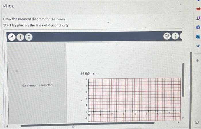
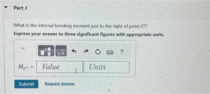
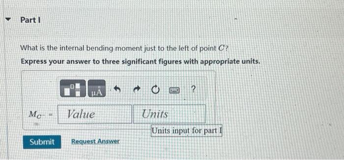
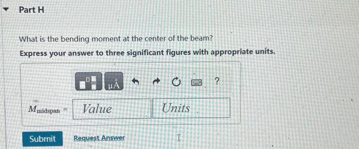
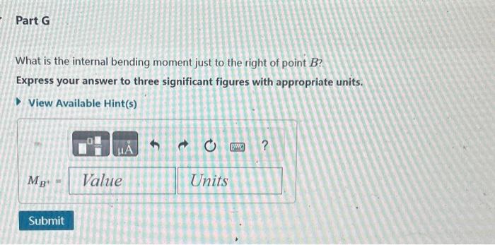
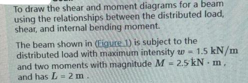
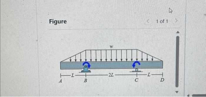
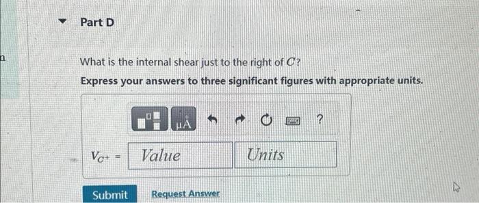
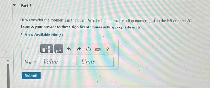
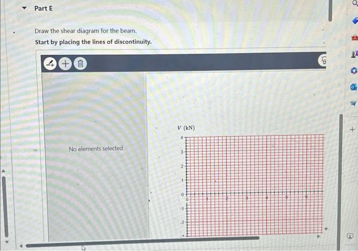
To draw the shear and moment diagrams for a beam using the relationships between the distributed load, shear, and internal bending moment. The beam shown in (Figure 1) is subject to the distributed load with maximum intensity w = 1.5 kN/m and two moments with magnitude M = 2.5 kN - m, and has L = 2 m. Figure A -B W -24- [0] C 1 of 1 -IL D 4 > Part D What is the internal shear just to the right of C? Express your answers to three significant figures with appropriate units. Vo+ H 0 A Value Submit Request Answer T Units ? Part E Draw the shear diagram for the beam. Start by placing the lines of discontinuity. +0 No elements selected V (kN) 4 3 2 1 0 0 -1- 2 9 1 B Part F Now consider the moments in the beam. What is the internal bending moment just to the left of point B? Express your answer to three significant figures with appropriate units. View Available Hint(s) MB Submit Value Units petic Part G What is the internal bending moment just to the right of point B? Express your answer to three significant figures with appropriate units. View Available Hint(s) MB Submit Value Units PW ? Part H What is the bending moment at the center of the beam? Express your answer to three significant figures with appropriate units. Mmidspan Submit A Value Request Answer Units I BAD ? Part I What is the internal bending moment just to the left of point C? Express your answer to three significant figures with appropriate units. Mc Submit PA Value Request Answer Units F Units input for part I Part J What is the internal bending moment just to the right of point C? Express your answer to three significant figures with appropriate units. MC+ HA Value Submit Request Answer O Units BRO Part K Draw the moment diagram for the beam. Start by placing the lines of discontinuity. +0 No elements selected M (kN-m) 5 4 3 2 1 0 0 i 2 E
Step by Step Solution
★★★★★
3.38 Rating (170 Votes )
There are 3 Steps involved in it
Step: 1
The skin friction coefficient Cf for a laminar boundary ...
Get Instant Access to Expert-Tailored Solutions
See step-by-step solutions with expert insights and AI powered tools for academic success
Step: 2

Step: 3

Ace Your Homework with AI
Get the answers you need in no time with our AI-driven, step-by-step assistance
Get Started


