Answered step by step
Verified Expert Solution
Question
1 Approved Answer
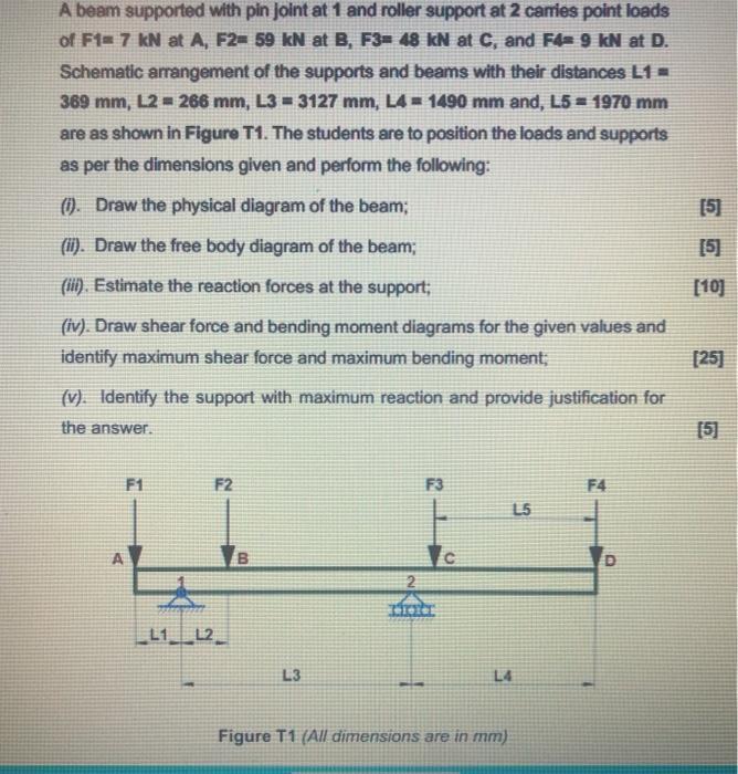
A beam supported with pin joint at 1 and roller support at 2 carries point loads of F1 7 kN at A, F2= 59


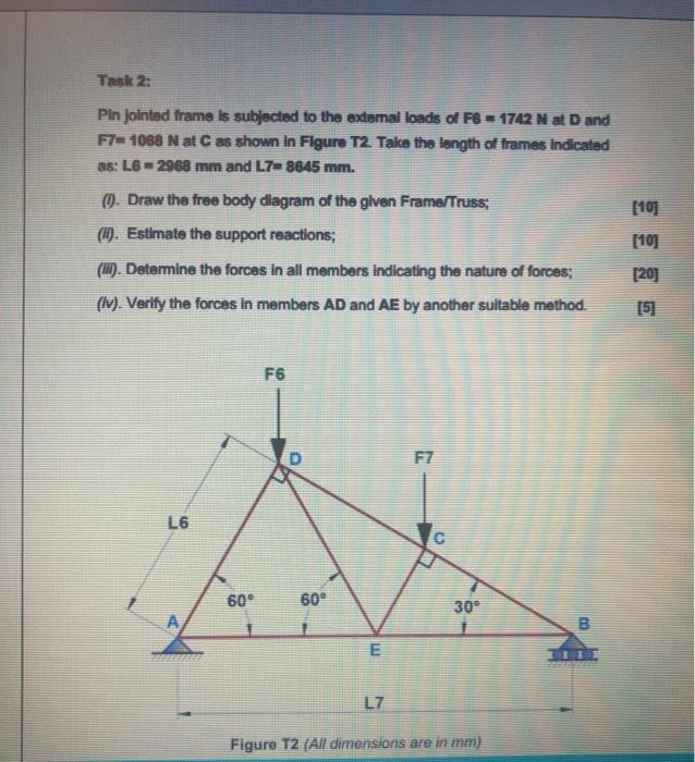
A beam supported with pin joint at 1 and roller support at 2 carries point loads of F1 7 kN at A, F2= 59 kN at B, F3= 48 kN at C, and F4- 9 kN at D. Schematic arrangement of the supports and beams with their distances L1 = 369 mm, L2= 266 mm, L3=3127 mm, L4 = 1490 mm and, L5 = 1970 mm are as shown in Figure T1. The students are to position the loads and supports as per the dimensions given and perform the following: (i). Draw the physical diagram of the beam; (ii). Draw the free body diagram of the beam; (iii). Estimate the reaction forces at the support; (iv). Draw shear force and bending moment diagrams for the given values and identify maximum shear force and maximum bending moment; (v). Identify the support with maximum reaction and provide justification for the answer. F1 A F2 L1 L2 L3 2 F3 L5 L4 Figure T1 (All dimensions are in mm) F4 D [5] [5] [10] [25] [5] Task 2: Pin jointed frame is subjected to the external loads of F8= 1742 N at D and F7- 1068 N at C as shown in Figure T2. Take the length of frames indicated as: L62968 mm and L7 8645 mm. (). Draw the free body diagram of the given Frame/Truss; (i). Estimate the support reactions; (ii). Determine the forces in all members indicating the nature of forces; (iv). Verify the forces in members AD and AE by another suitable method. L6 60 F6 60 E L7 F7 C 30 Figure T2 (All dimensions are in mm) B [10] [10] [20] [5]
Step by Step Solution
★★★★★
3.43 Rating (143 Votes )
There are 3 Steps involved in it
Step: 1
Solution Solution Beam Physical diagram F59 KM F 7KM ...
Get Instant Access to Expert-Tailored Solutions
See step-by-step solutions with expert insights and AI powered tools for academic success
Step: 2

Step: 3

Ace Your Homework with AI
Get the answers you need in no time with our AI-driven, step-by-step assistance
Get Started


