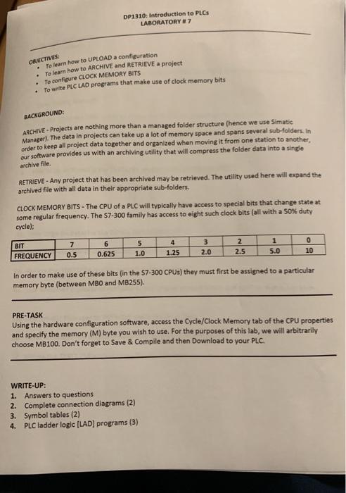
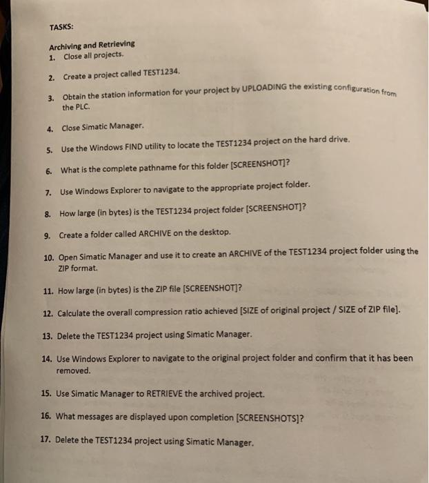
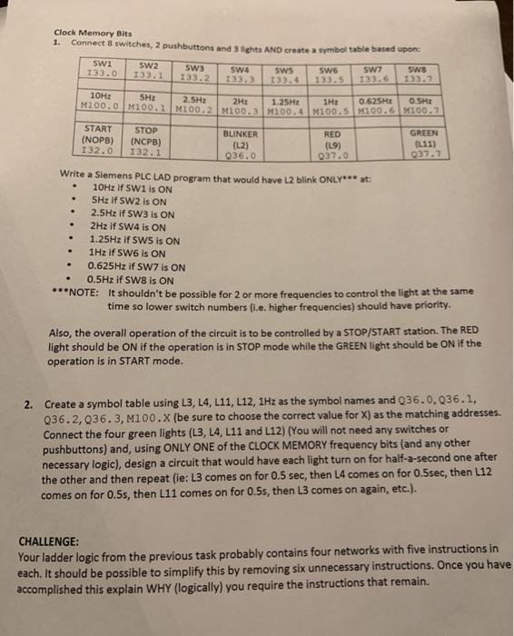
To learn how to ARCHIVE and RETRIEVE a project DP1310: Introduction to PLC LABORATORY #7 OBJECTIVES: To learn how to UPLOAD a configuration To configure CLOCK MEMORY BITS To write PLC LAD programs that make use of clock memory bits BACKGROUND: ARCHIVE - Projects are nothing more than a managed folder structure (hence we use Simatic Manager). The data in projects can take up a lot of memory space and spans several sub-folders. In order to keep all project data together and organized when moving it from one station to another, our software provides us with an archiving utility that will compress the folder data into a single archive file. RETRIEVE- Any project that has been archived may be retrieved. The utility used here will expand the archived file with all data in their appropriate sub-folders. CLOCK MEMORY BITS - The CPU of a PLC will typically have access to special bits that change state at some regular frequency. The S7-300 family has access to eight such clock bits (all with a 50% duty cycle): 7 BIT FREQUENCY 6 0.625 5 1.0 4 1.25 3 2.0 2 2.5 1 5.0 0 10 0.5 In order to make use of these bits (in the S7-300 CPUs) they must first be assigned to a particular memory byte (between MBO and MB255). PRE-TASK Using the hardware configuration software, access the Cycle/Clock Memory tab of the CPU properties and specify the memory (M) byte you wish to use. For the purposes of this lab, we will arbitrarily choose MB100. Don't forget to Save & Compile and then Download to your PLC. WRITE-UP: 1. Answers to questions 2. Complete connection diagrams (2) 3. Symbol tables (2) 4. PLC ladder logic (LAD) programs (3) TASKS: 3. Obtain the station information for your project by UPLOADING the existing configuration from the PLC. Archiving and Retrieving 1. Close all projects. 2. Create a project called TEST1234 4. Close Simatic Manager. 5. Use the Windows FIND utility to locate the TEST1234 project on the hard drive. 6. What is the complete pathname for this folder (SCREENSHOT]? 7. Use Windows Explorer to navigate to the appropriate project folder. 8. How large (in bytes) is the TEST1234 project folder [SCREENSHOT]? 9. Create a folder called ARCHIVE on the desktop. 10. Open Simatic Manager and use it to create an ARCHIVE of the TEST1234 project folder using the ZIP format 11. How large (in bytes) is the ZIP file (SCREENSHOT]? 12. Calculate the overall compression ratio achieved [SIZE of original project / SIZE of ZIP file). 13. Delete the TEST1234 project using Simatic Manager. 14. Use Windows Explorer to navigate to the original project folder and confirm that it has been removed. 15. Use Simatic Manager to RETRIEVE the archived project. 16. What messages are displayed upon completion (SCREENSHOTS]? 17. Delete the TEST1234 project using Simatic Manager. Clock Memory Bits 1. Connect 8 switches, 2 pushbuttons and 3 lights AND create a symbol table based upon SW1 SW2 SW3 SW4 SWS SW6 SWS 133.0 133.1 133.2 133.7 103.3 133.4 133.5 Sw7 10Hz 5H 2.5HE 2H: 1.25HE THE 0.625H OSHE M100.0 M200.1 M100.2 M100.3M100.4M100.5 M100.6 M100.7 START (NOPB) 132.0 STOP (NCPB) 132.1 BLINKER (L2) 036.0 RED (19) Q37.0 GREEN (L11) 037.7 . Write a Siemens PLC LAD program that would have L2 blink ONLY*** at: 10Hz If SW1 is ON 5Hz if SW2 is ON 2.5Hz if SW3 is ON 2Hz If SW4 is ON 1.25Hz if SW5 is ON 1Hz if SW6 is ON 0.625Hz if SW7 is ON 0.5Hz if SW8 is ON ***NOTE: It shouldn't be possible for 2 or more frequencies to control the light at the same time so lower switch numbers (i.e. higher frequencies) should have priority. Also, the overall operation of the circuit is to be controlled by a STOP/START station. The RED light should be on if the operation is in STOP mode while the GREEN light should be ON if the operation is in START mode. 2. Create a symbol table using L3, L4, L11, L12, 1Hz as the symbol names and 236.0,036.1, 236.2, 236.3, M100.x (be sure to choose the correct value for X) as the matching addresses. Connect the four green lights (L3, L4, L11 and L12) (You will not need any switches or pushbuttons) and using ONLY ONE of the CLOCK MEMORY frequency bits (and any other necessary logic), design a circuit that would have each light turn on for half-a-second one after the other and then repeat fie: L3 comes on for 0.5 sec, then 14 comes on for 0.5sec, then L12 comes on for 0.5s, then L11 comes on for 0.5s, then L3 comes on again, etc.). CHALLENGE: Your ladder logic from the previous task probably contains four networks with five instructions in each. It should be possible to simplify this by removing six unnecessary instructions. Once you have accomplished this explain WHY (logically) you require the instructions that remain. To learn how to ARCHIVE and RETRIEVE a project DP1310: Introduction to PLC LABORATORY #7 OBJECTIVES: To learn how to UPLOAD a configuration To configure CLOCK MEMORY BITS To write PLC LAD programs that make use of clock memory bits BACKGROUND: ARCHIVE - Projects are nothing more than a managed folder structure (hence we use Simatic Manager). The data in projects can take up a lot of memory space and spans several sub-folders. In order to keep all project data together and organized when moving it from one station to another, our software provides us with an archiving utility that will compress the folder data into a single archive file. RETRIEVE- Any project that has been archived may be retrieved. The utility used here will expand the archived file with all data in their appropriate sub-folders. CLOCK MEMORY BITS - The CPU of a PLC will typically have access to special bits that change state at some regular frequency. The S7-300 family has access to eight such clock bits (all with a 50% duty cycle): 7 BIT FREQUENCY 6 0.625 5 1.0 4 1.25 3 2.0 2 2.5 1 5.0 0 10 0.5 In order to make use of these bits (in the S7-300 CPUs) they must first be assigned to a particular memory byte (between MBO and MB255). PRE-TASK Using the hardware configuration software, access the Cycle/Clock Memory tab of the CPU properties and specify the memory (M) byte you wish to use. For the purposes of this lab, we will arbitrarily choose MB100. Don't forget to Save & Compile and then Download to your PLC. WRITE-UP: 1. Answers to questions 2. Complete connection diagrams (2) 3. Symbol tables (2) 4. PLC ladder logic (LAD) programs (3) TASKS: 3. Obtain the station information for your project by UPLOADING the existing configuration from the PLC. Archiving and Retrieving 1. Close all projects. 2. Create a project called TEST1234 4. Close Simatic Manager. 5. Use the Windows FIND utility to locate the TEST1234 project on the hard drive. 6. What is the complete pathname for this folder (SCREENSHOT]? 7. Use Windows Explorer to navigate to the appropriate project folder. 8. How large (in bytes) is the TEST1234 project folder [SCREENSHOT]? 9. Create a folder called ARCHIVE on the desktop. 10. Open Simatic Manager and use it to create an ARCHIVE of the TEST1234 project folder using the ZIP format 11. How large (in bytes) is the ZIP file (SCREENSHOT]? 12. Calculate the overall compression ratio achieved [SIZE of original project / SIZE of ZIP file). 13. Delete the TEST1234 project using Simatic Manager. 14. Use Windows Explorer to navigate to the original project folder and confirm that it has been removed. 15. Use Simatic Manager to RETRIEVE the archived project. 16. What messages are displayed upon completion (SCREENSHOTS]? 17. Delete the TEST1234 project using Simatic Manager. Clock Memory Bits 1. Connect 8 switches, 2 pushbuttons and 3 lights AND create a symbol table based upon SW1 SW2 SW3 SW4 SWS SW6 SWS 133.0 133.1 133.2 133.7 103.3 133.4 133.5 Sw7 10Hz 5H 2.5HE 2H: 1.25HE THE 0.625H OSHE M100.0 M200.1 M100.2 M100.3M100.4M100.5 M100.6 M100.7 START (NOPB) 132.0 STOP (NCPB) 132.1 BLINKER (L2) 036.0 RED (19) Q37.0 GREEN (L11) 037.7 . Write a Siemens PLC LAD program that would have L2 blink ONLY*** at: 10Hz If SW1 is ON 5Hz if SW2 is ON 2.5Hz if SW3 is ON 2Hz If SW4 is ON 1.25Hz if SW5 is ON 1Hz if SW6 is ON 0.625Hz if SW7 is ON 0.5Hz if SW8 is ON ***NOTE: It shouldn't be possible for 2 or more frequencies to control the light at the same time so lower switch numbers (i.e. higher frequencies) should have priority. Also, the overall operation of the circuit is to be controlled by a STOP/START station. The RED light should be on if the operation is in STOP mode while the GREEN light should be ON if the operation is in START mode. 2. Create a symbol table using L3, L4, L11, L12, 1Hz as the symbol names and 236.0,036.1, 236.2, 236.3, M100.x (be sure to choose the correct value for X) as the matching addresses. Connect the four green lights (L3, L4, L11 and L12) (You will not need any switches or pushbuttons) and using ONLY ONE of the CLOCK MEMORY frequency bits (and any other necessary logic), design a circuit that would have each light turn on for half-a-second one after the other and then repeat fie: L3 comes on for 0.5 sec, then 14 comes on for 0.5sec, then L12 comes on for 0.5s, then L11 comes on for 0.5s, then L3 comes on again, etc.). CHALLENGE: Your ladder logic from the previous task probably contains four networks with five instructions in each. It should be possible to simplify this by removing six unnecessary instructions. Once you have accomplished this explain WHY (logically) you require the instructions that remain


