Answered step by step
Verified Expert Solution
Question
1 Approved Answer
Topic: Microprocessor interfacing and embedded system Please solve a and b 1. (a) Explain how to access and configure individual bit as input for 8051
Topic: Microprocessor interfacing and embedded system
Please solve a and b
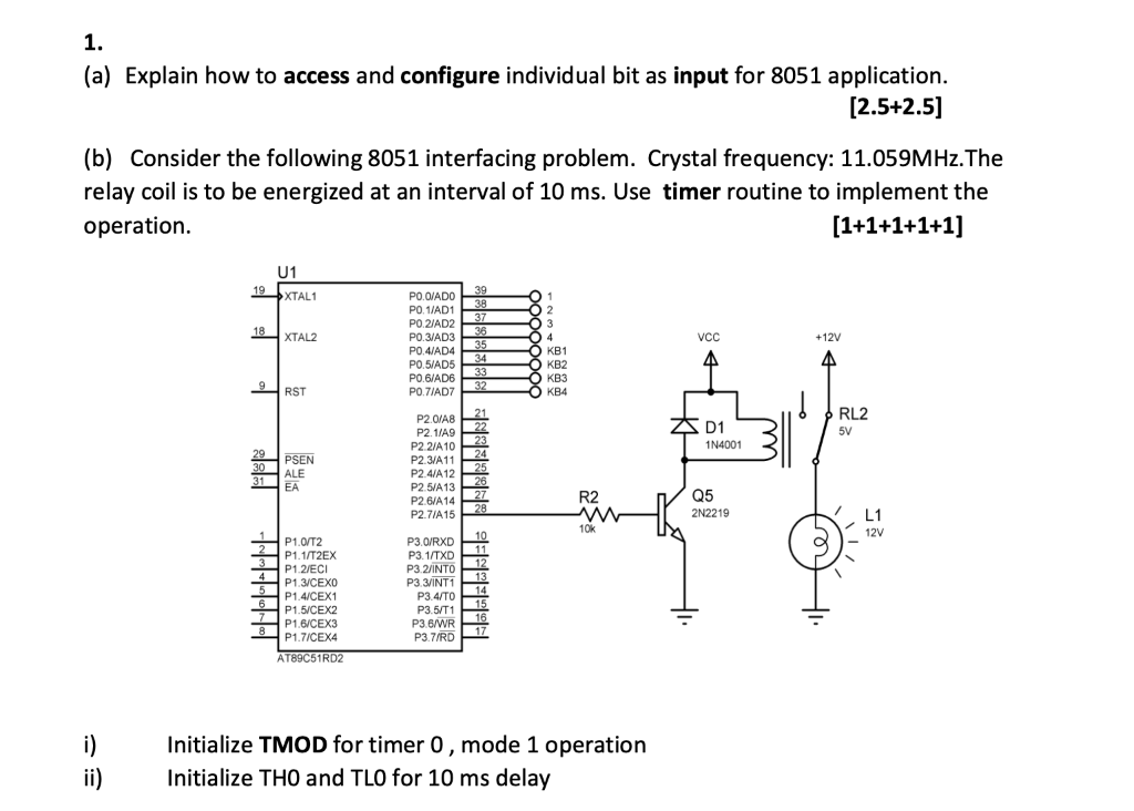
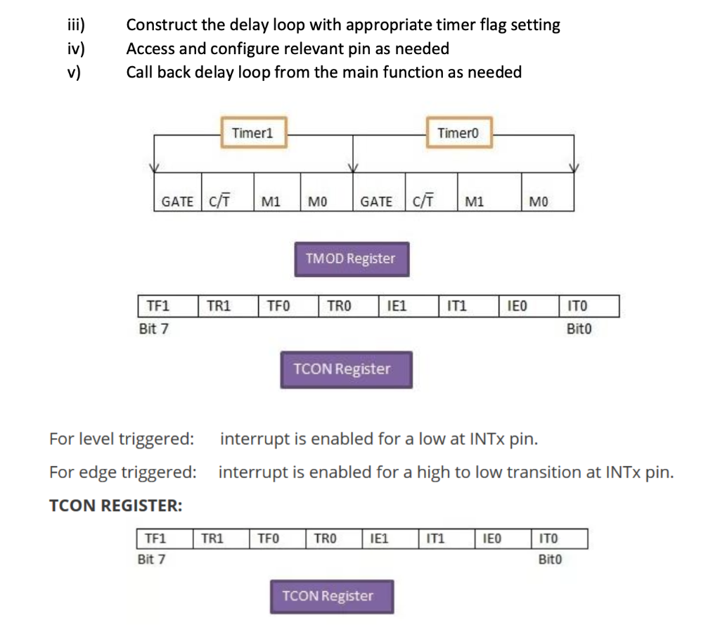
1. (a) Explain how to access and configure individual bit as input for 8051 application. [2.5+2.5] (b) Consider the following 8051 interfacing problem. Crystal frequency: 11.059MHz. The relay coil is to be energized at an interval of 10 ms. Use timer routine to implement the operation. [1+1+1+1+1] U1 19XTAL1 PO D/ADO PO 1/AD1 PO. AD2 39 38 37 18 XTAL2 PO.3/AD336 VCC +12V PO.4/AD4 / PO.5/AD5 PO 6/ADE PO.77AD7 35 34 33 32 0 1 2 03 04 OKB1 KB2 O KB3 OKB4 9RST D1 1N4001 RL2 5V 29PSEN 30 ALE 31 EA P2.0/AB P2.1/A9 P2 2/A 10 P2.3/A 11 P2.4/A12 P2.5/A13 P2.6/A14 P2 71/A15 21 22 23 24 25 26 27 28 R2 Q5 2N2219 10k L1 12V 2 3 4 5 6 P1.0/T2 P1.1/T2EX P1.2/ECI P1.3/CEXO P1.4/CEX1 P1.5/CEX2 P1.6/CEX3 P1.7/CEX4 P3.O/RXD P3.1/TXD P32/INTO P3 3/INTI P3.4/TO P3.5/T1 P3.B/WR P3.7/RD 10 11 12 13 14 15 16 17 8 AT89C51RD2 i) ii) Initialize TMOD for timer 0, mode 1 operation Initialize THO and TLO for 10 ms delay iii) iv) Construct the delay loop with appropriate timer flag setting Access and configure relevant pin as needed Call back delay loop from the main function as needed Timer1 Timero GATE C/T M1 MO GATE CT M1 MO TMOD Register TR1 TFO TRO IE1 IT1 IEO ITO TF1 Bit 7 Bito TCON Register For level triggered: interrupt is enabled for a low at INTx pin. For edge triggered: interrupt is enabled for a high to low transition at INTx pin. TCON REGISTER: TF1 TR1 TFO TRO IE1 IT1 IEO ITO Bito Bit 7 TCON RegisterStep by Step Solution
There are 3 Steps involved in it
Step: 1
Get Instant Access to Expert-Tailored Solutions
See step-by-step solutions with expert insights and AI powered tools for academic success
Step: 2
Step: 3
Ace Your Homework with AI
Get the answers you need in no time with our AI-driven, step-by-step assistance
Get Started