Question
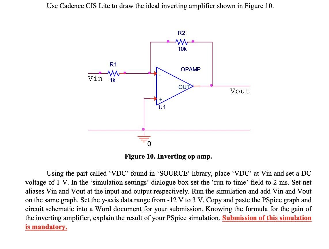
Use Cadence CIS Lite to draw the ideal inverting amplifier shown in Figure 10. R1 w Vin 1k U1 R2 ww 10k OPAMP OUD

Use Cadence CIS Lite to draw the ideal inverting amplifier shown in Figure 10. R1 w Vin 1k U1 R2 ww 10k OPAMP OUD 0 Figure 10. Inverting op amp. Vout Using the part called 'VDC' found in 'SOURCE' library, place 'VDC' at Vin and set a DC voltage of 1 V. In the 'simulation settings' dialogue box set the 'run to time' field to 2 ms. Set net aliases Vin and Vout at the input and output respectively. Run the simulation and add Vin and Vout on the same graph. Set the y-axis data range from -12 V to 3 V. Copy and paste the PSpice graph and circuit schematic into a Word document for your submission. Knowing the formula for the gain of the inverting amplifier, explain the result of your PSpice simulation. Submission of this simulation is mandatory.
Step by Step Solution
There are 3 Steps involved in it
Step: 1

Get Instant Access to Expert-Tailored Solutions
See step-by-step solutions with expert insights and AI powered tools for academic success
Step: 2

Step: 3

Ace Your Homework with AI
Get the answers you need in no time with our AI-driven, step-by-step assistance
Get StartedRecommended Textbook for
Schaum S Outline Of Electric Circuits
Authors: Mahmood Nahvi, Joseph Edminister
7th Edition
1260011968, 978-1260011968
Students also viewed these Programming questions
Question
Answered: 1 week ago
Question
Answered: 1 week ago
Question
Answered: 1 week ago
Question
Answered: 1 week ago
Question
Answered: 1 week ago
Question
Answered: 1 week ago
Question
Answered: 1 week ago
Question
Answered: 1 week ago
Question
Answered: 1 week ago
Question
Answered: 1 week ago
Question
Answered: 1 week ago
Question
Answered: 1 week ago
Question
Answered: 1 week ago
Question
Answered: 1 week ago
Question
Answered: 1 week ago
Question
Answered: 1 week ago
Question
Answered: 1 week ago
Question
Answered: 1 week ago
Question
Answered: 1 week ago
Question
Answered: 1 week ago
Question
Answered: 1 week ago
Question
Answered: 1 week ago
View Answer in SolutionInn App


