Question
Use the Matlab programs in Appendices as a starting point. Copy, paste and modify the code for the homework. Hand in the following as your
Use the Matlab programs in Appendices as a starting point. Copy, paste and modify the code for the homework.
Hand in the following as your submission for the homework:
- The program you modified.
- Resultant plots to show results you produced.
- Add caption with and parameters (weight, bias, activation function) to describe the result.
- Add a comment to summarize what you observed/learned from simulating the FNN.


yes I need the answer in Matlab, and answering the questions above. Do you want me to send you the Matlab code instead of image so you don't have to type it in? please let me know asap
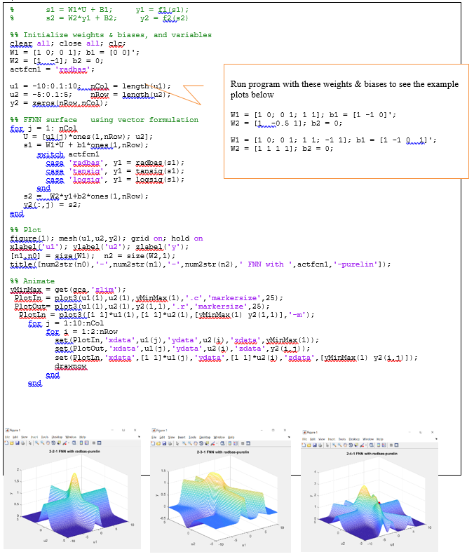
% MISO FF Neuron mapping
% s1 = W1*U + B1; y1 = f1(s1);
% s2 = W2*y1 + B2; y2 = f2(s2)
%% Initialize weights & biases, and variables
clear all; close all; clc;
W1 = [1 0; 0 1]; b1 = [0 0]';
W2 = [1 -1]; b2 = 0;
actfcn1 = 'radbas';
u1 = -10:0.1:10; nCol = length(u1);
u2 = -5:0.1:5; nRow = length(u2);
y2 = zeros(nRow,nCol);
%% FFNN surface using vector formulation
for j = 1: nCol
U = [u1(j)*ones(1,nRow); u2];
s1 = W1*U + b1*ones(1,nRow);
switch actfcn1
case 'radbas', y1 = radbas(s1);
case 'tansig', y1 = tansig(s1);
case 'logsig', y1 = logsig(s1);
end
s2 = W2*y1+b2*ones(1,nRow);
y2(:,j) = s2;
end
%% Plot
figure(1); mesh(u1,u2,y2); grid on; hold on
xlabel('u1'); ylabel('u2'); zlabel('y');
[n1,n0] = size(W1); n2 = size(W2,1);
title([num2str(n0),'-',num2str(n1),'-',num2str(n2),' FNN with ',actfcn1,'-purelin']);
%% Animate
yMinMax = get(gca,'zlim');
PlotIn = plot3(u1(1),u2(1),yMinMax(1),'.c','markersize',25);
PlotOut= plot3(u1(1),u2(1),y2(1,1),'.r','markersize',25);
PlotLn = plot3([1 1]*u1(1),[1 1]*u2(1),[yMinMax(1) y2(1,1)],'-m');
for j = 1:10:nCol
for i = 1:2:nRow
set(PlotIn,'xdata',u1(j),'ydata',u2(i),'zdata',yMinMax(1));
set(PlotOut,'xdata',u1(j),'ydata',u2(i),'zdata',y2(i,j));
set(PlotLn,'xdata',[1 1]*u1(j),'ydata',[1 1]*u2(i),'zdata',[yMinMax(1) y2(i,j)]);
drawnow
end
end
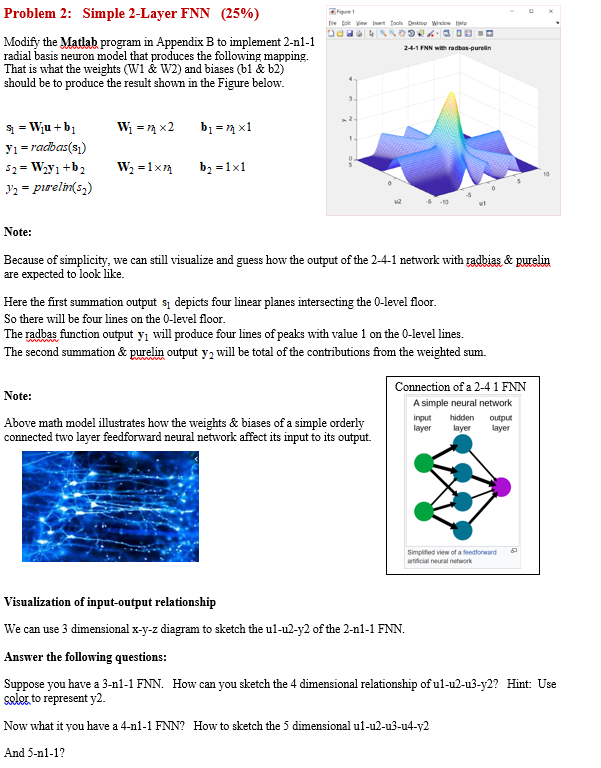
Problem 2: Simple 2-Layer FNN (25%) Daas .30 24-1 NN with redbus purelin Modify the Matlab program in Appendix B to implement 2-n1-1 radial basis neuron model that produces the following mapping. That is what the weights (W1 & W2) and biases (bl & b2) should be to produce the result shown in the Figure below. ; = 1 x2 b = 24 x1 S = Wju+ b Y1 = radbas(si) 52 = W2y +b2 y2 = purelin(52) W2 = 1xm b2 =1x1 Note: Because of simplicity, we can still visualize and guess how the output of the 2-4-1 network with radbias & purelin are expected to look like. Here the first summation output si depicts four linear planes intersecting the O-level floor. So there will be four lines on the O-level floor. The radbas function output y will produce four lines of peaks with value 1 on the O-level lines. The second summation & purelin output y2 will be total of the contributions from the weighted sum. Note: Connection of a 2-4 1 FNN A simple neural network input hidden output layer layer layer Above math model illustrates how the weights & biases of a simple orderly connected two layer feedforward neural network affect its input to its output. Simplified view of a feedforward artificial al network Visualization of input-output relationship We can use 3 dimensional x-y-z diagram to sketch the ul-u2-y2 of the 2-n1-1 FNN. Answer the following questions: Suppose you have a 3-n1-1 FNN. How can you sketch the 4 dimensional relationship of ul-u2-u3-y2? Hint: Use color to represent y2. Now what it you have a 4-n1-1 FNN? How to sketch the 5 dimensional ul-u2-u3-u4-v2 And 5-n1-12 sl = W1W + B1; 32 = W2*yl + B2; yi - Fus1); y2 = F292) $$ Initialize weights & biases, and variables slear all, close all; sis; W1 = [1 0; 0 1]; b1 = [0 0]'; W2 = [ 1 1 ]; b2 = 0; actfoni = 'adrea'; ul = -10:0.1:10 i ncol = length (ul); Run program with these weights & biases to see the example u2 = -5:0.1:5; non = Lengthlu2), plots below Y2 = zeker Besencem) W1 = (1 0; O 1; 1 1]; b1 = [1 -1 0]'; $$ FENN surface using vector formulation W2 = (1 -0.5 1]; b2 = 0; For i = 1: need U = (ul) +ones (1, now); u2]; s1 = W1*U + b1*anes (1, now); wi = [1 0; 0 1; 1 1; -1 1]; b1 = [1 -1 dl '; W2 = [1 1 1 1]; b2 = 0; axitch actfoni Saze 'sadbea', y1 = kadasa (sl); Saze 'tanzig', yi = tanaig (sl); Sass Lessig', y1 = legaig (51); end s262*y1+b2*ones (1, nrow); 2 , 3) = 32; end ** Plot figure 1); mesh (ul, u2, 72); grid on; hold on xlabel'ul'); slabel('2'); label('y'); [ni ] = size (W1); n2 = size (2, 1); titlel (num2 str (no), '-', num2str(nl),'-', num2 str (n2),' ENN with ', actfoni,'-purelin']); $$ Animate MinMax = get (gca, 'sim'); Rlot In = plot 3 (ul(1), u2(1), MinMax(1),'.c', 'markersize', 25); Rlotout= plot 3. (ul(1), u2(1), 72(1,1),'.r', 'markersize', 25); Platio = RIREZ11 1] *u1(1), [1 1] -u2(1), [yMinmax(1) y2(1,1)],'-m'); Fra j = 1:10:nCol FBK i = 1:2:nRow set PlotIn, 'xdata', u1(j), 'ydata', u2(1), 'zdata', MinMax (1)); 26. Plotout, 'xdata', ui(j), 'ydata', u2(1), 'zdata',y2( ); set (Blatin, 'xdate', [1 1] -ui(j), 'date', [1 1] *u2 (i), 'sdata', CyMinMax (1) y2 )]); Sg Bad O & G DE 24. FNN with purelin Problem 2: Simple 2-Layer FNN (25%) Daas .30 24-1 NN with redbus purelin Modify the Matlab program in Appendix B to implement 2-n1-1 radial basis neuron model that produces the following mapping. That is what the weights (W1 & W2) and biases (bl & b2) should be to produce the result shown in the Figure below. ; = 1 x2 b = 24 x1 S = Wju+ b Y1 = radbas(si) 52 = W2y +b2 y2 = purelin(52) W2 = 1xm b2 =1x1 Note: Because of simplicity, we can still visualize and guess how the output of the 2-4-1 network with radbias & purelin are expected to look like. Here the first summation output si depicts four linear planes intersecting the O-level floor. So there will be four lines on the O-level floor. The radbas function output y will produce four lines of peaks with value 1 on the O-level lines. The second summation & purelin output y2 will be total of the contributions from the weighted sum. Note: Connection of a 2-4 1 FNN A simple neural network input hidden output layer layer layer Above math model illustrates how the weights & biases of a simple orderly connected two layer feedforward neural network affect its input to its output. Simplified view of a feedforward artificial al network Visualization of input-output relationship We can use 3 dimensional x-y-z diagram to sketch the ul-u2-y2 of the 2-n1-1 FNN. Answer the following questions: Suppose you have a 3-n1-1 FNN. How can you sketch the 4 dimensional relationship of ul-u2-u3-y2? Hint: Use color to represent y2. Now what it you have a 4-n1-1 FNN? How to sketch the 5 dimensional ul-u2-u3-u4-v2 And 5-n1-12 sl = W1W + B1; 32 = W2*yl + B2; yi - Fus1); y2 = F292) $$ Initialize weights & biases, and variables slear all, close all; sis; W1 = [1 0; 0 1]; b1 = [0 0]'; W2 = [ 1 1 ]; b2 = 0; actfoni = 'adrea'; ul = -10:0.1:10 i ncol = length (ul); Run program with these weights & biases to see the example u2 = -5:0.1:5; non = Lengthlu2), plots below Y2 = zeker Besencem) W1 = (1 0; O 1; 1 1]; b1 = [1 -1 0]'; $$ FENN surface using vector formulation W2 = (1 -0.5 1]; b2 = 0; For i = 1: need U = (ul) +ones (1, now); u2]; s1 = W1*U + b1*anes (1, now); wi = [1 0; 0 1; 1 1; -1 1]; b1 = [1 -1 dl '; W2 = [1 1 1 1]; b2 = 0; axitch actfoni Saze 'sadbea', y1 = kadasa (sl); Saze 'tanzig', yi = tanaig (sl); Sass Lessig', y1 = legaig (51); end s262*y1+b2*ones (1, nrow); 2 , 3) = 32; end ** Plot figure 1); mesh (ul, u2, 72); grid on; hold on xlabel'ul'); slabel('2'); label('y'); [ni ] = size (W1); n2 = size (2, 1); titlel (num2 str (no), '-', num2str(nl),'-', num2 str (n2),' ENN with ', actfoni,'-purelin']); $$ Animate MinMax = get (gca, 'sim'); Rlot In = plot 3 (ul(1), u2(1), MinMax(1),'.c', 'markersize', 25); Rlotout= plot 3. (ul(1), u2(1), 72(1,1),'.r', 'markersize', 25); Platio = RIREZ11 1] *u1(1), [1 1] -u2(1), [yMinmax(1) y2(1,1)],'-m'); Fra j = 1:10:nCol FBK i = 1:2:nRow set PlotIn, 'xdata', u1(j), 'ydata', u2(1), 'zdata', MinMax (1)); 26. Plotout, 'xdata', ui(j), 'ydata', u2(1), 'zdata',y2( ); set (Blatin, 'xdate', [1 1] -ui(j), 'date', [1 1] *u2 (i), 'sdata', CyMinMax (1) y2 )]); Sg Bad O & G DE 24. FNN with purelinStep by Step Solution
There are 3 Steps involved in it
Step: 1

Get Instant Access to Expert-Tailored Solutions
See step-by-step solutions with expert insights and AI powered tools for academic success
Step: 2

Step: 3

Ace Your Homework with AI
Get the answers you need in no time with our AI-driven, step-by-step assistance
Get Started


