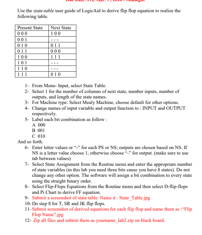
Use the state-table user guide of LogicAid to derive flip flop equation to realize the following table Present StateNext State 1 00 00 1 010 011 1 00 10 1 110 011 010 1- From Menu- Input, select State Table 2- Select 1 for the number of columns of next state, number inputs, number of outputs, and length of the state names 3- For Machine type: Select Mealy Machine, choose default for other options. 4- Change names of input variable and output function to INPUT and OUTPUT respectively 5- Label each bit combination as follow: A 000 B 001 C 010 And so forth. 6- Enter letter values or "" for each PS or NS; outputs are chosen based on NS. If for output. (make sure to use NS is a letter value choose 1, otherwise choose tab between values) 7- Select State Assignment from the Routine menu and enter the appropriate number of state variables (in this lab you need three bits cause you have 8 states). Do not change any other option. The software will assign a bit combination to every state using the straight binary order 8- Select Flip-Flops Equations from the Routine menu and then select D-flip-flops and Pi Chart to derive FF equation. 9- Submit a screenshot of state table. Name it State Table.jpg 10-Do step 8 for T, SR and JK flip flops 11- Submit screenshot of derived equations for each flip flop and name them as :"Flip Flop Name" jpg 12- Zip all files and submit them as yourname_lab2.zip on black board. Use the state-table user guide of LogicAid to derive flip flop equation to realize the following table Present StateNext State 1 00 00 1 010 011 1 00 10 1 110 011 010 1- From Menu- Input, select State Table 2- Select 1 for the number of columns of next state, number inputs, number of outputs, and length of the state names 3- For Machine type: Select Mealy Machine, choose default for other options. 4- Change names of input variable and output function to INPUT and OUTPUT respectively 5- Label each bit combination as follow: A 000 B 001 C 010 And so forth. 6- Enter letter values or "" for each PS or NS; outputs are chosen based on NS. If for output. (make sure to use NS is a letter value choose 1, otherwise choose tab between values) 7- Select State Assignment from the Routine menu and enter the appropriate number of state variables (in this lab you need three bits cause you have 8 states). Do not change any other option. The software will assign a bit combination to every state using the straight binary order 8- Select Flip-Flops Equations from the Routine menu and then select D-flip-flops and Pi Chart to derive FF equation. 9- Submit a screenshot of state table. Name it State Table.jpg 10-Do step 8 for T, SR and JK flip flops 11- Submit screenshot of derived equations for each flip flop and name them as :"Flip Flop Name" jpg 12- Zip all files and submit them as yourname_lab2.zip on black board


