

Question: using https://www.edaplayground.com DESIGN PROCEDURE: Note that for each Verilog design task a dassignX_X.sv and optionally dassignX_X.tb are provided. The .v file contains the module you
using https://www.edaplayground.com DESIGN PROCEDURE: Note that for each Verilog design task a dassignX_X.sv and optionally dassignX_X.tb are provided. The .v file contains the module you are to design. You are to fill in these modules for each design task.
The XYZ_tb.v files are test benches that tests your design.
File provided: dassign2.sv, led_fsm.sv, code_reg.sv, ascii_morse.txt, test benches for each. In this design assignment, the goal of is to implement a Morse Code encoder that lights an
LED accordingly. The LED is represented by a signal LED_DRV.
In Morse Code, Dash (-) is 3 continuous time units of beep and Dot (.) is 1 time unit of beep. Dots and Dashes are separated by 1 time unit. Space between characters can be 2 or 3 time units. A space between words is indicated by at least 7 consecutive time units of blank.
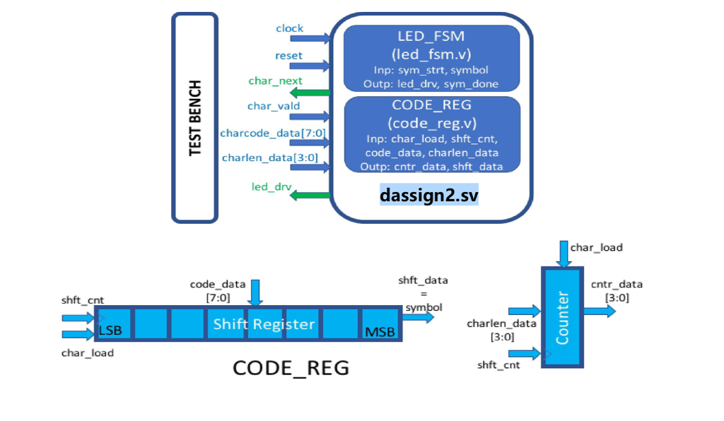
The figure below shows a block diagram of the design. The test bench will specify a 3-kbit memory that maps 8-bit ASCII symbols (2 hexadecimal digits) into 12-bit outputs. A file that contains the mapping of the desired set of ASCII symbols to Morse Code is provided (ascii_morse.txt). The test bench will output to your code (dassign3.v) two inputs, charcode_data[7:0] and charlen_data[3:0]. The bus, charcode_data[7:0], is a sequence of 1s and 0s where a 1 represents a Dash and a 0 represents a Dot for a given character. The charlen_data[3:0] is a binary representation of the length of the sequence for that character. Note that charlen_data=4b0001 represents a length of 1. For example,
| Character | Morse Code | charcode_data[7:0] | charlen_data[3:0] |
| A | .- | 8b01XXXXXX | 4b0010 |
| E | . | 8b0XXXXXXX | 4b0001 |
| I | .. | 8b00XXXXXX | 4b0010 |
|
| / | 8bXXXXXXXX | 4b0000 |
Note that the X (dont care) in the memory are loaded as 0s, hence the charcode_data can be the same for letters such as I and E if not for the differences in charlen_data. Space between words is a special character (8h20 in ASCII) and is demarked by charlen_data=4b0000.
A state diagram of a Mealy FSM that handles either of the 2 Morse symbols is shown below. At the SYM_START(initial) state, if the input SYM_STRT=1b1, the FSM transitions to either a Dot or a Dash depending on the input SYMBOL value of 1b1 or 1b0. When outputting a Dash, the output signal LED_DRV is driven to 1b1 for 3 cycles and then OFF for 1 cycle before starting the next symbol. Similarly, when outputting a Dot, the output signal LED_DRV is driven to 1b1 for 1 cycle and then OFF for 1 cycle before starting the next symbol. When the LED turns off, a signal SYM_DONE=1b1 is asserted for 1 cycle.
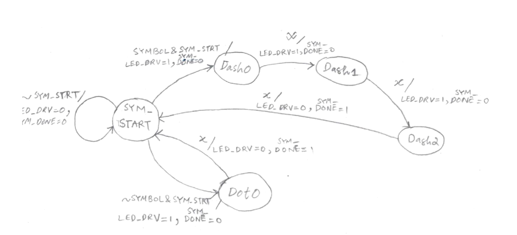
First, write the Verilog code for the state machines to implement the Dash and Dot symbols of Morse Code. This corresponds to the module led_fsm (LED_FSM). To make your timing easier for the final step of the project you should assert the LED_DRV signal on the arc leaving the START state. That way you can have your output respond more quickly to an input symbol. Note that inputs clock and reset are not shown in the figure. Proper behavior of this FSM should result in no more than 1 blank cycle between DASH or DOT symbols for a given character. The test bench tests for this.
Next, implement a module code_reg (CODE_REG shown in the figure below) contains two blocks: (a) an 8-bit shift register that is holds charcode_data[7:0] and (b) a 4-bit counter that is loaded with the charlen_data[3:0]. Note that inputs clock and reset are not shown in the figure. Both blocks take a 1-bit input signal, char_load. The signal when asserted, loads the shift register with charcode_data, and loads the counter with charlen_data. The MSB of the shift register is also the output shft_data which indicates the symbol that needs to be decoded by the LED_FSM corresponding to Morse Dot or Dash. The 4-bit output, cntr_data[3:0], is the value held in the counter. You should assume that char_load is asserted for only 1 cycle. When char_load is not asserted, the input signal, shft_cnt, is used to trigger both the shift register and counter. The shift register shifts left (toward the MSB) for every clock cycle that shft_cnt is asserted which changes the shft_data correspondingly. The counter counts down for each cycle that shft_cnt is asserted. Note that to handle a space symbol, you can choose to load the counter with 4b0111 so that the counter can be used to count down.
Finally, the main module, dassign2 (MORSE_ENCODER), takes inputs corresponding to the character it is to encode (charcode_data and charlen_data), an output that drives an LED (led_drv) to light up based on the code, and some handshaking signals. A clock signal, clock, and a reset signal, reset, are provided where reset is a synchronous reset that brings all FSMs into its starting/initial position. The input clock is the primary synchronizing signal. To handshake between the testbench and your module, a char_vald=1b1 for 1 clock cycle accompanies the charcode_data and charlen_data to indicate the code to be valid for encoding so that you can load the registers and start your state machine. The MORSE_ENCODER should determine when to count down or shift the blocks in CODE_REG. When cntr_data reaches 4b0000, the encoding of the character is considered complete. When the module completes a character, a
char_next is asserted to 1b1 to request the next character. The test bench receives this request and makes available the next character to be encoded (loaded) and the char_vald is asserted. The char_next remains asserted until a new char_vald arrives. Because space is a special character, charlen_data=4b0000 needs to be identified and handled properly.
Proper behavior of the MORSE_ENCODER should result in consecutive characters to be transmitted. Each character has symbols (DASH or DOT) that are separated by not more than 1 blank cycle. Between characters, 2 or 3 blank cycles are permitted. Between words, an explicit space character is provided and should be at least 7 blank cycles and should not exceed 12 blank cycles.
The MORSE_ENCODER module is yours to design. You may choose to use another FSM to perform the sequencing for handshaking for the next character, handling each symbol, and handling a space. You may choose to create another module to do this.
dassign2.sv
Since the design has three parts, you will write led_fsm.sv, code_reg.sv and dassign2.sv. Three different test benches are provided to test each of these three parts. These test benches provided is also the test bench for the grader so make sure that your design works without modifying the test benches. You can of course test other combinations.
led_fsm_sv:
// Code your design here
////////////////////////////////////////////////////////////////
// module LED FSM
////////////////////////////////////////////////////////////////
`timescale 1ns/1ps
module led_fsm(
input sym_strt, symbol,
output led_drv, sym_done,
input reset, clock
);
////////////////////////////////////////////////////////////////
// parameter declarations
////////////////////////////////////////////////////////////////
parameter START=3'b000;
parameter DASH0=3'b001;
parameter DASH1=3'b010;
parameter DASH2=3'b011;
parameter DOT0 =3'b100;
////////////////////////////////////////////////////////////////
// State register for FSM
////////////////////////////////////////////////////////////////
reg [2:0] led_st;
always @(posedge clock) begin
led_st
end
////////////////////////////////////////////////////////////////
// State and Output logic for statemachine
////////////////////////////////////////////////////////////////
reg [2:0] led_nx_st;
reg led_drv, sym_done; //outputs you need to generate
// data transfer
always @ * begin
if ( reset == 1'b1 )
led_nx_st = START;
else begin
case ( led_st )
// your code here
endcase
end
end
// output sym_done
always @ * begin
if ( reset == 1'b1 )
sym_done = 1'b0;
else begin
// your code here
end
end
// output led_drv
always @ * begin
if ( reset == 1'b1 )
led_drv = 1'b0;
else begin
// your code here
end
end
endmodule // led_fsm
code_reg.sv:
////////////////////////////////////////////////////////////////
// module CODE REG
////////////////////////////////////////////////////////////////
/*
There are 2 blocks to implement here. A counter and a shift register.
Inputs (charcode_data and charlen_data) that represent the signal to be
encoded is loaded into these two elements to be processed.
The shifter loads its values (charcode_data) with the signal char_load.
The shifter shifts to MSB whenever the signal shft_cnt is received.
The counter loads the value charlen_data into its registers by the signal
char_load.
The counter counts down whenever the signal shft_cnt is received.
One way to handle a "space" in the code is to load into the counter 4'b0111
whenever you see a charlen_data = 4'b0000. That way you can use the
counter to count the number of blanks needed
*/
`timescale 1ns/1ps
module code_reg(
input [7:0] charcode_data,
input [3:0] charlen_data,
input char_load, shft_cnt,
output [3:0] cntr_data,
output shft_data,
input reset, clock
);
////////////////////////////////////////////////////////////////
// state register/FF for counter (cntr) and shifter (shftr)
////////////////////////////////////////////////////////////////
reg [7:0] shftr;
reg [3:0] cntr;
// shift register with reset and load
always @(posedge clock) begin
// your code here
end
// counter with reset and load
always @(posedge clock) begin
// your code here
end
assign cntr_data = cntr; // counter output
assign shft_data = shftr[7]; // shifter output
endmodule // code_reg
dassign2.sv:
// Code your design here
`include "led_fsm.sv"
`include "code_reg.sv"
////////////////////////////////////////////////////////////////
// Main File for dassign32
////////////////////////////////////////////////////////////////
////////////////////////////////////////////////////////////////
// module dassign2 (also MORSE_ENCODER)
////////////////////////////////////////////////////////////////
`timescale 1ns/1ps
module dassign2(
input char_vald,
input [7:0] charcode_data,
input [3:0] charlen_data,
output char_next, led_drv,
input reset, clock
);
////////////////////////////////////////////////////////////////
// Parameter Declarations
////////////////////////////////////////////////////////////////
////////////////////////////////////////////////////////////////
// Variable Declaration
////////////////////////////////////////////////////////////////
// Outputs from modules
wire shft_data, sym_done, led_drv;
wire [3:0] cntr_data;
// Signals that needs to be generated by this module
wire char_next, shft_cnt;
reg [3:0] charlen_modified;
reg sym_strt;
wire char_load;
////////////////////////////////////////////////////////////////
// Module Instantiation
////////////////////////////////////////////////////////////////
code_reg U_code_reg (
.charcode_data ( charcode_data ),
.charlen_data ( charlen_data ),
.char_load ( char_load ),
.shft_cnt ( shft_cnt ),
.cntr_data ( cntr_data ),
.shft_data ( shft_data ),
.reset ( reset ),
.clock ( clock )
);
led_fsm U_led_fsm (
.sym_strt ( sym_strt ),
.symbol ( shft_data ),
.led_drv ( led_drv ),
.sym_done ( sym_done ),
.reset ( reset ),
.clock ( clock )
);
// ******************************************************************
// Some useful pseudo-code
//
// symbol for led_fsm = shft_data from the shifter
// sym_strt is asserted when char_vald or after you've shifted
// a new data symbol from the shifter
//
// space symbol is detected when charlen_data = 4'b0000
// shft_cnt is asserted when sym_done is asserted (if using the
// counter to deal with a space, you'd need to enable shft_cnt for
// a "space" symbol)
//
// char_next for encoder = cntr counts down to 0
// (load counter with 4'b0111 when it is a space either in
// code_reg or here)
// char_ vald input should trigger the char_load to grab the new
// charcode_data and charlen_data
// ******************************************************************
// Your Code Here
endmodule // dassign2
SYM- SYMBOL &SYM-STRT YM Da SYM SYM START Daghd ~SYMBOL SYM, ST SY SYM- SYMBOL &SYM-STRT YM Da SYM SYM START Daghd ~SYMBOL SYM, ST SY
Step by Step Solution
There are 3 Steps involved in it

Get step-by-step solutions from verified subject matter experts