Answered step by step
Verified Expert Solution
Question
1 Approved Answer
Using R134a as the working fluid and the operating conditions provided Consider the rig without a regenerator (state 7) where the flow goes directly from

Using R134a as the working fluid and the operating conditions provided
Consider the rig without a regenerator (state 7) where the flow goes directly from the compressor (state 1) to heat exchanger 3 (state 4), then calculate the following:
i) thermal efficiency of the cycle
ii) net power output
iii) Rate of heat transfer to the refrigerant in every heat exchanger
iv) rate of heat transfer from refrigerant to the cooling water in the condenser
v) mass flow rate of cooling water in the condenser
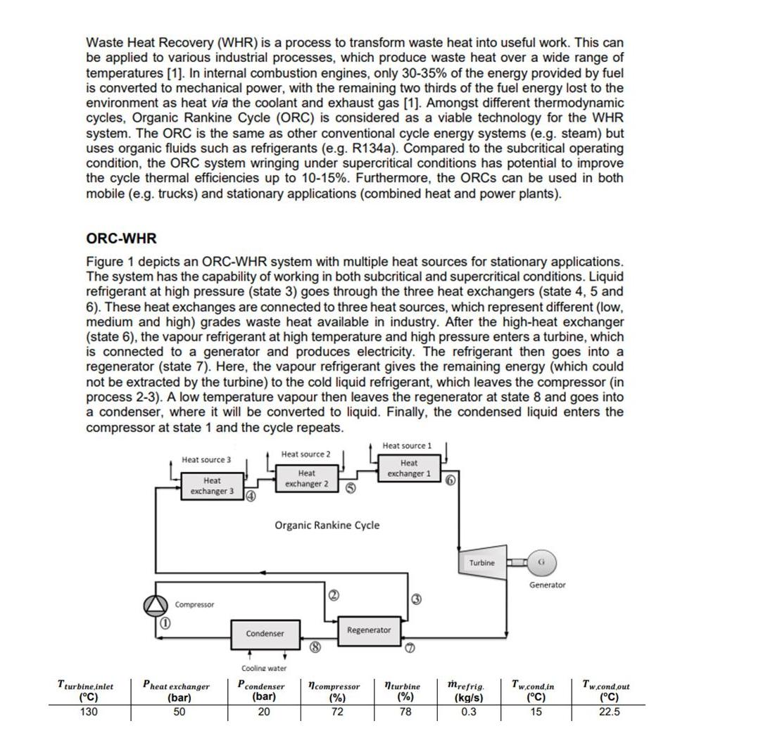
Waste Heat Recovery (WHR) is a process to transform waste heat into useful work. This can be applied to various industrial processes, which produce waste heat over a wide range of temperatures [1]. In internal combustion engines, only 30-35% of the energy provided by fuel is converted to mechanical power, with the remaining two thirds of the fuel energy lost to the environment as heat via the coolant and exhaust gas [1]. Amongst different thermodynamic cycles, Organic Rankine Cycle (ORC) is considered as a viable technology for the WHR system. The ORC is the same as other conventional cycle energy systems (e.g. steam) but uses organic fluids such as refrigerants (e.g. R134a). Compared to the subcritical operating condition, the ORC system wringing under supercritical conditions has potential to improve the cycle thermal efficiencies up to 10-15%. Furthermore, the ORCS can be used in both mobile (e.g. trucks) and stationary applications (combined heat and power plants). ORC-WHR Figure 1 depicts an ORC-WHR system with multiple heat sources for stationary applications. The system has the capability of working in both subcritical and supercritical conditions. Liquid refrigerant at high pressure (state 3) goes through the three heat exchangers (state 4, 5 and 6). These heat exchanges are connected to three heat sources, which represent different (low, medium and high) grades waste heat available in industry. After the high-heat exchanger (state 6), the vapour refrigerant at high temperature and high pressure enters a turbine, which is connected to a generator and produces electricity. The refrigerant then goes into a regenerator (state 7). Here, the vapour refrigerant gives the remaining energy (which could not be extracted by the turbine) to the cold liquid refrigerant, which leaves the compressor (in process 2-3). A low temperature vapour then leaves the regenerator at state 8 and goes into a condenser, where it will be converted to liquid. Finally, the condensed liquid enters the compressor at state 1 and the cycle repeats. Tturbine inlet (C) 130 (1) Heat source 3 Heat exchanger 3 Compressor Pheat exchanger (bar) 50 (4 Heat source 2 Heat exchanger 2 Organic Rankine Cycle Condenser * Cooling water Pcondenser (bar) 20 2 Heat source 1 Heat exchanger 1 6 Regenerator G ncompressor nturbine (%) (%) 72 78 Turbine I mrefrig. (kg/s) 0.3 G Generator Tw.cond.in (C) 15 Tw.cond out (C) 22.5
Step by Step Solution
★★★★★
3.46 Rating (146 Votes )
There are 3 Steps involved in it
Step: 1

Get Instant Access to Expert-Tailored Solutions
See step-by-step solutions with expert insights and AI powered tools for academic success
Step: 2

Step: 3

Ace Your Homework with AI
Get the answers you need in no time with our AI-driven, step-by-step assistance
Get Started


