

Question: Using the requirements and equipment given please complete 1 - 4 : 1 ) A function table of D Flip Flop containing both present state
Using the requirements and equipment given please complete :
A function table of D Flip Flop containing both present state Q and next state Q;
State table for complete operation A table contains input xpresent states of CBAnext states
of CBAoutput zand present D Flip Flop inputs DDand D;
Kmaps to obtain Boolean equations of DDDand zand the application of DeMorgans to convert them into NAND gate and AND gate formats;
Built a circuit diagram
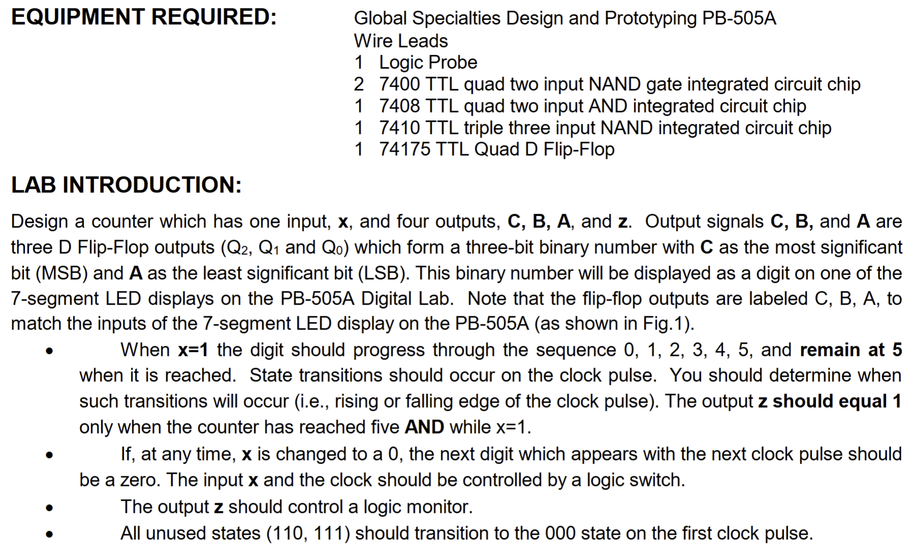
EQUIPMENT REQUIRED:
Global Specialties Design and Prototyping PBA
Wire Leads
Logic Probe
TTL quad two input NAND gate integrated circuit chip
TTL quad two input AND integrated circuit chip
TTL triple three input NAND integrated circuit chip
TTL Quad D FlipFlop
LAB INTRODUCTION:
Design a counter which has one input, x and four outputs, CBA and z Output signals CB and A are
three D FlipFlop outputs QQ and Q which form a threebit binary number with C as the most significant
bit MSB and A as the least significant bit LSB This binary number will be displayed as a digit on one of the
segment LED displays on the PBA Digital Lab. Note that the flipflop outputs are labeled C B A to
match the inputs of the segment LED display on the PBA as shown in Fig
When x the digit should progress through the sequence and remain at
when it is reached. State transitions should occur on the clock pulse. You should determine when
such transitions will occur ie rising or falling edge of the clock pulse The output z should equal
only when the counter has reached five AND while x
If at any time, x is changed to a the next digit which appears with the next clock pulse should
be a zero. The input x and the clock should be controlled by a logic switch.
quad The output z should control a logic monitor.
quad All unused states should transition to the state on the first clock pulse.
Step by Step Solution
There are 3 Steps involved in it
1 Expert Approved Answer
Step: 1 Unlock

Question Has Been Solved by an Expert!
Get step-by-step solutions from verified subject matter experts
Step: 2 Unlock
Step: 3 Unlock