Question
VerilogQuestion VerilogQuestionVerilogQuestionVerilogQuestionVerilogQuestionVerilogQuestionVerilogQuestionVerilogQuestionVerilogQuestionVerilogQuestionVerilogQuestionVerilogQuestionVerilogQuestionVerilogQuestionVerilogQuestionVerilogQuestionVerilogQuestionVerilogQuestionVerilogQuestionVerilogQuestionVerilogQuestionVerilogQuestionVerilogQuestionVerilogQuestionVerilogQuestionVerilogQuestionVerilogQuestionVerilogQuestionVerilogQuestionVerilogQuestionVerilogQuestionVerilogQuestionVerilogQuestionVerilogQuestionVerilogQuestionVerilogQuestionVerilogQuestionVerilogQuestionVerilogQuestionVerilogQuestionVerilogQuestionVerilogQuestionVerilogQuestionVerilogQuestionVerilogQuestionVerilogQuestionVerilogQuestionVerilogQuestionVerilogQuestionVerilogQuestionVerilogQuestionVerilogQuestion Write a module just for kpdecode (*make sure you put output ct[3:0]): The kpdecode module is a combinational module that determines which if
VerilogQuestion VerilogQuestionVerilogQuestionVerilogQuestionVerilogQuestionVerilogQuestionVerilogQuestionVerilogQuestionVerilogQuestionVerilogQuestionVerilogQuestionVerilogQuestionVerilogQuestionVerilogQuestionVerilogQuestionVerilogQuestionVerilogQuestionVerilogQuestionVerilogQuestionVerilogQuestionVerilogQuestionVerilogQuestionVerilogQuestionVerilogQuestionVerilogQuestionVerilogQuestionVerilogQuestionVerilogQuestionVerilogQuestionVerilogQuestionVerilogQuestionVerilogQuestionVerilogQuestionVerilogQuestionVerilogQuestionVerilogQuestionVerilogQuestionVerilogQuestionVerilogQuestionVerilogQuestionVerilogQuestionVerilogQuestionVerilogQuestionVerilogQuestionVerilogQuestionVerilogQuestionVerilogQuestionVerilogQuestionVerilogQuestionVerilogQuestionVerilogQuestionVerilogQuestion

Write a module just for kpdecode (*make sure you put output ct[3:0]):
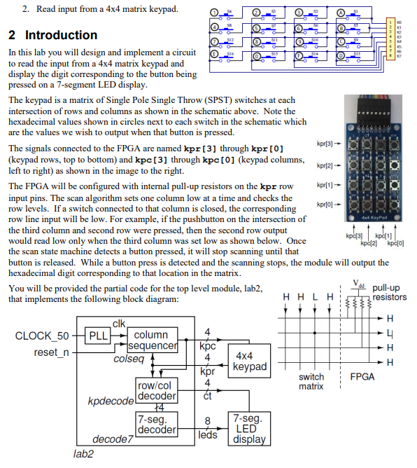
The kpdecode module is a combinational module that determines which if any button is pressed based on the kpr and kpc signals. When a button press is detected, the module will assign the num output the corresponding 4-bit value of the key pressed (0 to F) and set the kphit output signal high. The kphit signal will be used to drive the ct[0] output to turn on the least-significant digit of the LED display only when a button is pressed.
*Please do not copy from solution that is already in this chegg. I want to see another approach.
kpr[3] - kpr[0] LOAD 4x4 Keypad 2. Read input from a 4x4 matrix keypad. 2 Introduction In this lab you will design and implement a circuit to read the input from a 4x4 matrix keypad and display the digit corresponding to the button being pressed on a 7-segment LED display. The keypad is a matrix of Single Pole Single Throw (SPST) switches at each intersection of rows and columns as shown in the schematic above. Note the hexadecimal values shown in circles next to each switch in the schematic which are the values we wish to output when that button is pressed. The signals connected to the FPGA are named kpr [3] through kpr [0] (keypad rows, top to bottom) and kpc [3] through kpc [0] (keypad columns, kpr(2) left to right) as shown in the image to the right. The FPGA will be configured with internal pull-up resistors on the kpr row kpr[1] input pins. The scan algorithm sets one column low at a time and checks the row levels. If a switch connected to that column is closed, the corresponding row line input will be low. For example, if the pushbutton on the intersection of the third column and second row were pressed, then the second row output would read low only when the third column was set low as shown below. Once kp[3] kp.[2] the scan state machine detects a button pressed, it will stop scanning until that button is released. While a button press is detected and the scanning stops, the module will output the hexadecimal digit corresponding to that location in the matrix. You will be provided the partial code for the top level module, lab2, that implements the following block diagram: HHLH resistors H clk CLOCK_50 PLL column 4 4 reset_n sequencer kpc colseq 4 4x4 H kpr keypad FPGA 4 row/col kpdecode! decoderi t 14 7-seg 8 7-seg. decoder LED decode 7 lab2 kpc[0] pull-up switch matrix leds displayStep by Step Solution
There are 3 Steps involved in it
Step: 1

Get Instant Access to Expert-Tailored Solutions
See step-by-step solutions with expert insights and AI powered tools for academic success
Step: 2

Step: 3

Ace Your Homework with AI
Get the answers you need in no time with our AI-driven, step-by-step assistance
Get Started


