

Question: We were given the data below and told to come up with everything else on our own based on the data given. (we did not
We were given the data below and told to come up with everything else on our own based on the data given. (we did not have the materials for the lab so we are doing it this way. Just pretending it is being done and coming up with answers based on what was given) Honestly, I'm not asking for all of this. Just anything you think you can help me with.
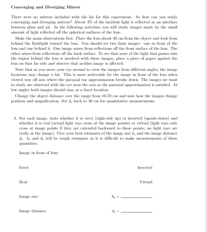
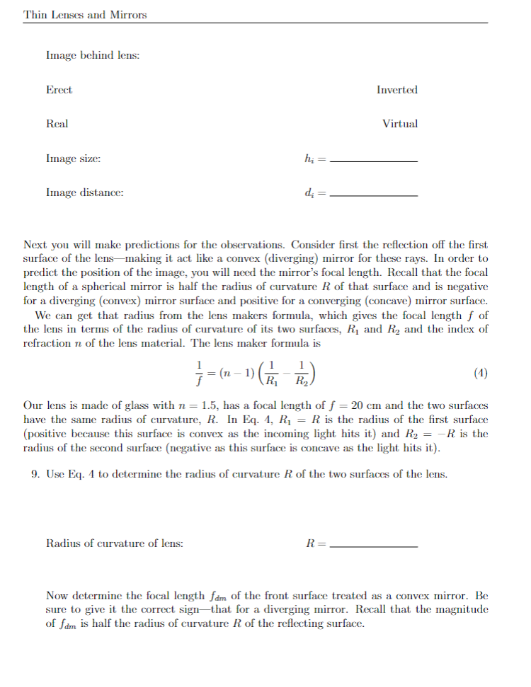
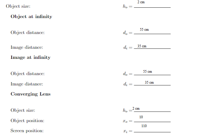
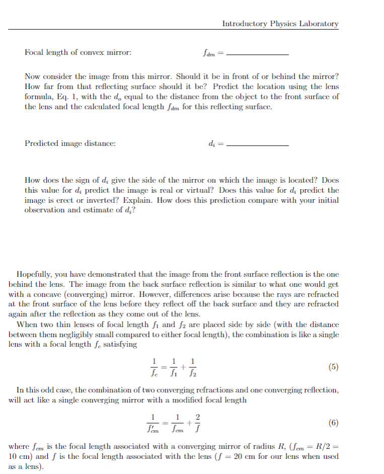
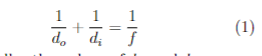
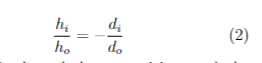
Converging and Diverging Mirror There were no mirrors included with the kit for this experiment. So how can you study converging and diverging mirrors? About 1% of the incident light is reflected at an interface between glass and air. In the following activities you will study images made by the small amount of light reflected off the spherical surfaces of the lens. Make the main observations first. Place the lens about 10 cm from the object and look from behind the flashlight toward the lens. You should see two faint images one in front of the lens and one behind it. One image arises from reflections off the front surface of the lens. The other arises from reflections off the back surface. To see that none of the light that passes into the region behind the lens is involved with these images, place a piece of paper against the lens on that far side and observe that neither image is affected. Note that as you move your eye around to view the images from different angles, the image locations may change a bit. This is more noticeable for the image in front of the lens when viewed way off axis where the paraxial ray approximation breaks down. The images we want to study are observed with the eye near the axis so the paraxial approximation is satisfied. At low angles both images should stay at a fixed location. Change the object distance over the range from 10-70 cm and note how the images change position and magnification. Set do back to 10 cm for quantitative measurements. 8. For each image, state whether it is erect (right-side up) or inverted (upside-down) and whether it is real (actual light rays cross at the image points) or virtual (light rays only cross at image points if they are extended backward to those points; no light rays are really at the image). Give your best estimates of the image size h, and the image distance di. h; and di will be rough estimates as it is difficult to make measurements of these quantities. Image in front of lens: Erect Inverted Real Virtual Image size: ha = Image distance: di = _Thin Lenses and Mirrors Image behind lens: Erect Inverted Real Virtual Image size: hi = Image distance: di = Next you will make predictions for the observations. Consider first the reflection off the first surface of the lens-making it act like a convex (diverging) mirror for these rays. In order to predict the position of the image, you will need the mirror's focal length. Recall that the focal length of a spherical mirror is half the radius of curvature R of that surface and is negative for a diverging (convex) mirror surface and positive for a converging (concave) mirror surface. We can get that radius from the lens makers formula, which gives the focal length f of the lens in terms of the radius of curvature of its two surfaces, R, and R2 and the index of refraction n of the lens material. The lens maker formula is 7 = (20 - 1) ( 71 , 763) (1) Our lens is made of glass with n = 1.5, has a focal length of f = 20 cm and the two surfaces have the same radius of curvature, R. In Eq. 4, R, = R is the radius of the first surface (positive because this surface is convex as the incoming light hits it) and R2 = -R is the radius of the second surface (negative as this surface is concave as the light hits it). 9. Use Eq. 4 to determine the radius of curvature R of the two surfaces of the lens. Radius of curvature of lens: R = Now determine the focal length fam of the front surface treated as a convex mirror. Be sure to give it the correct sign-that for a diverging mirror. Recall that the magnitude of fam is half the radius of curvature R of the reflecting surface.2 cm Object size: ho = Object at infinity 55 cm Object distance: do = Image distance: di = 35 cm Image at infinity Object distance: 55 cm do = - Image distance: di =- 35 cm Converging Lens Object size: h, = 2 cm 10 Object position: 110 Screen position: I=Introductory Physics Laboratory Focal length of convex mirror: fam = Now consider the image from this mirror. Should it be in front of or behind the mirror? How far from that reflecting surface should it be? Predict the location using the lens formula, Eq. 1, with the do equal to the distance from the object to the front surface of the lens and the calculated focal length fam for this reflecting surface. Predicted image distance: di = How does the sign of di give the side of the mirror on which the image is located? Does this value for di predict the image is real or virtual? Does this value for d; predict the image is erect or inverted? Explain. How does this prediction compare with your initial observation and estimate of d;? Hopefully, you have demonstrated that the image from the front surface reflection is the one behind the lens. The image from the back surface reflection is similar to what one would get with a concave (converging) mirror. However, differences arise because the rays are refracted at the front surface of the lens before they reflect off the back surface and they are refracted again after the reflection as they come out of the lens. When two thin lenses of focal length fi and f2 are placed side by side (with the distance between them negligibly small compared to either focal length), the combination is like a single lens with a focal length fe satisfying 1 (5) In this odd case, the combination of two converging refractions and one converging reflection, will act like a single converging mirror with a modified focal length (6) where fem is the focal length associated with a converging mirror of radius R, (fem = R/2 = 10 cm) and f is the focal length associated with the lens (f = 20 cm for our lens when used as a lens)-10. Determine the modified focal length of the back surface reflection. Modified focal length: fem = Set the object distance to 10 cm and then use the modified focal length to get a predicted image distance. Predicted image distance: di = How does the sign of di above imply that the image is in front of the lens? Remember this is a case of a converging mirror. How does the magnitude of d; compare with your initial observations where you estimated this distance? Take into account your guess as to the expected accuracy of your estimate. In addition, the formula for the modified focal length f' is a "thin lens" formula, whereas our lens is about 1.5 cm thick-not all that small compared to the focal lengths and image distances for these observations. More exact calculations show the image distance can be expected to be shorter than the thin-lens prediction by about 0.5 cm. For fun... Is there any way you could make the real image in front of the lens appear on a screen? You can't put up a big screen as that would block the light from the flashlight to the lens. However, it can be done with a small paddle-shaped screen-with the paddle head not much bigger than the image and with the handle thin and long enough to hold it without blocking the light with you hand. It will be pretty dim and you will need a darkened room to see it.+ (1) do2 FF M (3
Step by Step Solution
There are 3 Steps involved in it

Get step-by-step solutions from verified subject matter experts