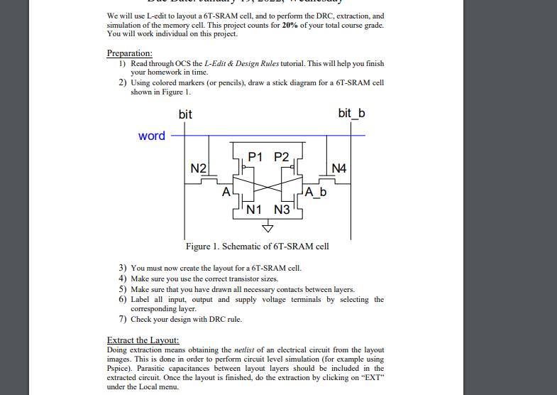
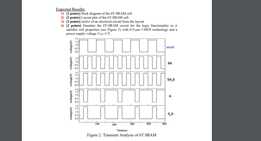
We will use L-edit to layout a 6T-SRAM cell, and to perform the DRC, extraction, and simulation of the memory cell. This project counts for 20% of your total course grade. You will work individual on this project. Preparation: 1) Read through OCS the L-Edit & Design Rules tutorial. This will help you finish your homework in time. 2) Using colored markers (or pencils), draw a stick diagram for a 6T-SRAM cell shown in Figure 1. bit bit_b word P1 P2 N2 N4 A JA_b N1 N3 Figure 1. Schematic of 6T-SRAM cell 3) You must now create the layout for a 6T-SRAM cell. 4) Make sure you use the correct transistor sizes. 5) Make sure that you have drawn all necessary contacts between layers. 6) Label all input, output and supply voltage terminals by selecting the corresponding layer. 7) Check your design with DRC rule. Extract the Layout: Doing extraction means obtaining the netlist of an electrical circuit from the layout images. This is done in order to perform circuit level simulation (for example using Pspice). Parasitic capacitances between layout layers should be included in the extracted circuit. Once the layout is finished, do the extraction by clicking on "EXT" under the Local menu. Expected Results: 1) 12 points Stick diagram of the 6T-SRAM cell. 2) 13 points Layout plot of the 6T-SRAM cell. 3) 12 points netlist of an electrical circuit from the layout. 4) 12 points Simulate the 6T-SRAM circuit for the logic functionality so it satisfies cell properties (see Figure 2) with 0.5-um CMOS technology and a power supply voltage V3 V. 3.0 1.5 word 10 0.5 0.0 OOOOOOOON 1.5 1.0 05 bit bit_b M voltage(V) voltage(V) 30 1.5 1.0 0.5 00 3.0 1.5 10 0.5 0.0 30 1.5 1.0 0.5 0.0 A voltage(V) A_b 100 200 300 400 500 Timeins) Figure 2. Transient Analysis of 6T SRAM 5) 12 points) From the transient analysis measure the propagation delay values from the midpoint of the input word waveform (the midpoint of the voltage at the word) to the midpoint of output bit line (bit) for read operation. A fair amount of precision is required on this assignment to get the correct values, so use cursors when you are determining propagation delays. Now repeat measurement for the rising and falling portions of the waveform. Hand in your propagation-delay values. 6) (2 points From the transient analysis measure the propagation delay values from the midpoint of the input word waveform to the midpoint of SRAM cell content (A) for write operation. Repeat measurement for the rising and falling portions of the waveform. Hand in your propagation-delay values. 7) [4 points] From the transient analysis measure the dynamic and leakage power values. 8) [3 points Please turn in your SPICE code along with the waveforms. 2