What are the schematics to build a clock using seven segment displays? I have all required parts but would like help creating the schematics.

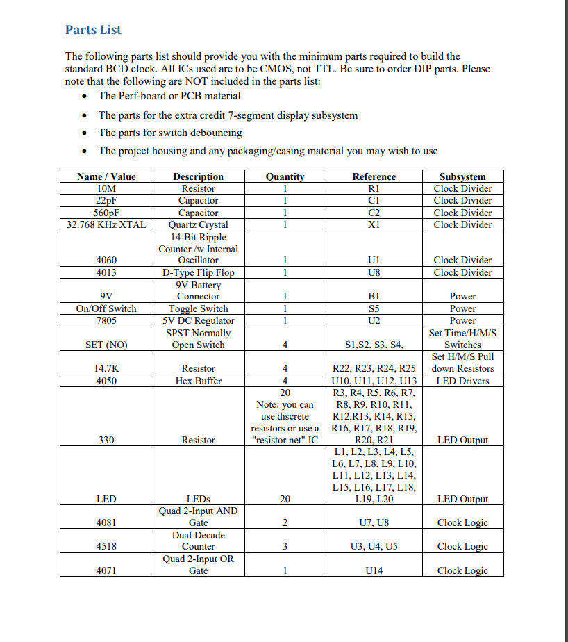
Parts List The following parts list should provide you with the minimum parts required to build the standard BCD clock. All ICs used are to be CMOS, not TTL. Be sure to order DIP parts. Please note that the following are NOT included in the parts list: The Perf-board or PCB material The parts for the extra credit 7-segment display subsystem The parts for switch debouncing The project housing and any packaging/casing material you may wish to use Ouantity Reference Name / Value 10M 22pF Subsystem Clock Divider Clock Divider Clock Divider Clock Divider 560pF 32.768 KHz XTAL 4060 4013 Description Resistor Capacitor Capacitor Quartz Crystal 14-Bit Ripple Counter /w Internal Oscillator | D-Type Flip Flop 9V Battery Connector Toggle Switch 5V DC Regulator SPST Normally Open Switch Clock Divider Clock Divider 9V SS On/Off Switch 7805 U2 SET (NO) Power Power Power Set Time/H/M/S Switches Set H/M/S Pull down Resistors LED Drivers S1,S2, S3, S4, 14.7K 4050 Resistor Hex Buffer 4 20 Note: you can use discrete resistors or use a "resistor net" IC R22, R23, R24, R25 U10, U11, U12, U13 R3, R4, R5, R6, R7, R8, R9, R10, RII, R12,R13, R14, R15, R16, R17, R18, R19, R20, R21 L1, L2, L3, L4, L5, L6, L7, L8, L9, L10, L11, L12, L13, L14, L15, L16, L17, L18, L19, L20 330 Resistor LED Output LED LED Output |4081 U7, U8 Clock Logic LEDs Quad 2-Input AND Gate Dual Decade Counter Quad 2-Input OR Gate 4518 U3, U4, U5 Clock Logic 4071 U14 Clock Logic Parts List The following parts list should provide you with the minimum parts required to build the standard BCD clock. All ICs used are to be CMOS, not TTL. Be sure to order DIP parts. Please note that the following are NOT included in the parts list: The Perf-board or PCB material The parts for the extra credit 7-segment display subsystem The parts for switch debouncing The project housing and any packaging/casing material you may wish to use Ouantity Reference Name / Value 10M 22pF Subsystem Clock Divider Clock Divider Clock Divider Clock Divider 560pF 32.768 KHz XTAL 4060 4013 Description Resistor Capacitor Capacitor Quartz Crystal 14-Bit Ripple Counter /w Internal Oscillator | D-Type Flip Flop 9V Battery Connector Toggle Switch 5V DC Regulator SPST Normally Open Switch Clock Divider Clock Divider 9V SS On/Off Switch 7805 U2 SET (NO) Power Power Power Set Time/H/M/S Switches Set H/M/S Pull down Resistors LED Drivers S1,S2, S3, S4, 14.7K 4050 Resistor Hex Buffer 4 20 Note: you can use discrete resistors or use a "resistor net" IC R22, R23, R24, R25 U10, U11, U12, U13 R3, R4, R5, R6, R7, R8, R9, R10, RII, R12,R13, R14, R15, R16, R17, R18, R19, R20, R21 L1, L2, L3, L4, L5, L6, L7, L8, L9, L10, L11, L12, L13, L14, L15, L16, L17, L18, L19, L20 330 Resistor LED Output LED LED Output |4081 U7, U8 Clock Logic LEDs Quad 2-Input AND Gate Dual Decade Counter Quad 2-Input OR Gate 4518 U3, U4, U5 Clock Logic 4071 U14 Clock Logic


