Question: Whenever a lab asks you to assemble a circuit, and measure some quantities, implement (capture) the circuit in MultiSim, and use its simulation tools to
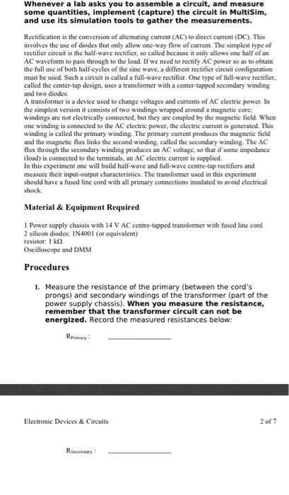
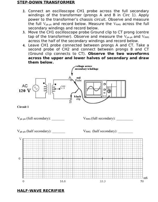
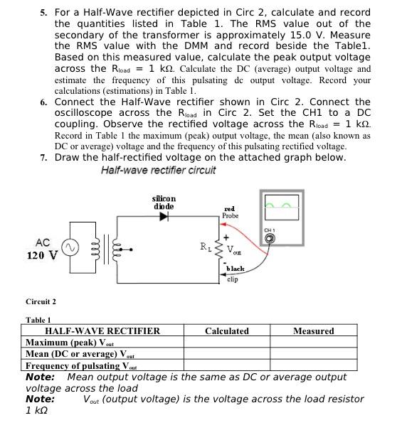
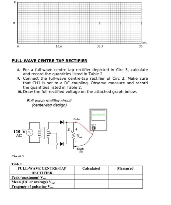
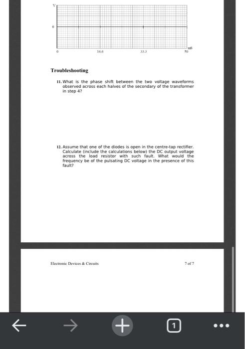
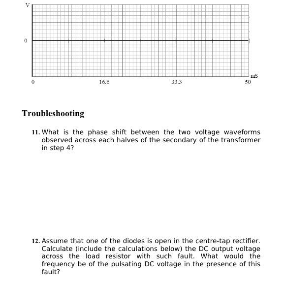
Whenever a lab asks you to assemble a circuit, and measure some quantities, implement (capture) the circuit in MultiSim, and use its simulation tools to gather the measurements. Rectification is the conversion of alternating current (AC) to direct current (DC). This involves the use of diodes that only allow one-way flow of current. The simplest type of rectifier circuit is the half-wave rectifier, so called because it only allows one half of an AC waveform to pass through to the load. If we need to rectify AC power so as to obtain the full use of both half-cycles of the sine wave a different rectifier circuit configuration must be used. Such a circuit is called a full-wave rectifier. One type of full-wave rectifier. called the center-tap design, uses a transformer with a center-tapped secondary winding and two diodes. A transformer is a device used to change voltages and currents of AC electric power. In the simplest version it consists of two windings wrapped around a magnetic core: windings are not electrically connected, but they are coupled by the magnetic field. When one winding is connected to the AC electric power, the electric current is generated. This winding is called the primary winding. The primary current produces the magnetic field and the magnetic flux links the second winding, called the secondary winding. The AC flux through the secondary winding produces an AC voltage, so that if some impedance (load) is connected to the terminals, an AC clectric current is supplied. In this experiment one will build half-wave and full-wave centre-tap rectifiers and measure their input-output characteristics. The transformer used in this experiment should have a fused line cord with all primary connections insulated to avoid electrical shock Material & Equipment Required 1 Power supply chassis with 14 V AC centre-tapped transformer with fused line cord 2 silicon diodes: 1N4001 (or equivalent) resistor: 1 Oscilloscope and DMM Procedures 1. Measure the resistance of the primary (between the cord's prongs) and secondary windings of the transformer (part of the power supply chassis). When you measure the resistance, remember that the transformer circuit can not be energized. Record the measured resistances below: Remary Electronic Devices & Circuits 2 of 7 Rsecondary STEP-DOWN TRANSFORMER 2. Connect an oscilloscope CH1 probe across the full secondary windings of the transformer (prongs A and B in Circ 1). Apply power to the transformer's chassis circuit. Observe and measure the full Vpk ok and record below. Measure the Vams across the full secondary windings and record below. 3. Move the CH1 oscilloscope probe Ground clip to CT prong (centre tap of the transformer). Observe and measure the Vpk-pik and VRMS across the half of the secondary windings and record below. 4. Leave CH1 probe connected between prongs A and CT. Take a second probe of CH2 and connect between prongs B and CT (Ground clip connects to CT). Observe the two waveforms across the upper and lower halves of secondary and draw them below. voltage across secondary windings red Probe AC 120 V CT black clip Circuit 1 Vok-pk (full secondary): Vams (full secondary): Vpk pk (half secondary): VAMS (half secondary): V 0 ms 50 0 16.6 33.3 HALF-WAVE RECRIFIER 5. For a Half-Wave rectifier depicted in Circ 2, calculate and record the quantities listed in Table 1. The RMS value out of the secondary of the transformer is approximately 15.0 V. Measure the RMS value with the DMM and record beside the Table1. Based on this measured value, calculate the peak output voltage across the Rives = 1 k.2. Calculate the DC (average) output voltage and estimate the frequency of this pulsating de output voltage. Record your calculations (estimations) in Table 1. 6. Connect the Half-Wave rectifier shown in Circ 2. Connect the oscilloscope across the Road in Circ 2. Set the CH1 to a DC coupling. Observe the rectified voltage across the Road = 1 ko. Record in Table 1 the maximum (peak) output voltage, the mean (also known as DC or average) voltage and the frequency of this pulsating rectified voltage. 7. Draw the half-rectified voltage on the attached graph below. Haif-wave rectifier circuit silicon diode red Probe AC 120 V L le Ru Van ORT black clip Circuit 2 Table 1 HALF-WAVE RECTIFIER Calculated Measured Maximum (peak) Vu Mean (DC or average) Vu Frequency of pulsating out Note: Mean output voltage is the same as DC or average output voltage across the load Note: Vout (output voltage) is the voltage across the load resistor 1 v 0 nes 0 16.6 333 50 FULL-WAVE CENTRE-TAP RECTIFIER 8. For a full-wave centre-tap rectifier depicted in Circ 3, calculate and record the quantities listed in Table 2. 9. Connect the full-wave centre-tap rectifier of Circ 3. Make sure that CH1 is set to a DC coupling. Observe measure and record the quantities listed in Table 2. 10. Draw the full rectified voltage on the attached graph below. Full-wave rectifier circuit (center-tap design) Probe 0 R 120 V AC black clip Circuit 3 Calculated Measured Table 2 FULL-WAVE CENTRE-TAP RECTIFIER Peak (maximum) V. Mean (DC or average) V.. Freqency of pulsating V 16.6 Troubleshooting 11. What is the phase shift between the two voltage waveforms observed across each halves of the secondary of the transformer in step 47 12. Assume that one of the diodes is open in the centre-tap rectifier. Calculate (include the calculations below) the DC output voltage across the load resistor with such fault. What would the frequency be of the pulsating DC voltage in the presence of this fault? Electronic Devices & Circuits 767 + V 0 ms 0 16.6 33.3 50 Troubleshooting 11. What is the phase shift between the two voltage waveforms observed across each halves of the secondary of the transformer in step 4? 12. Assume that one of the diodes is open in the centre-tap rectifier. Calculate (include the calculations below) the DC output voltage across the load resistor with such fault. What would the frequency be of the pulsating DC voltage in the presence of this fault
Step by Step Solution
There are 3 Steps involved in it

Get step-by-step solutions from verified subject matter experts


