Answered step by step
Verified Expert Solution
Question
1 Approved Answer
Write a VHDL code file that uses a 3 input 2 output encoder. draw a block diagram to go along with the VHDL code and


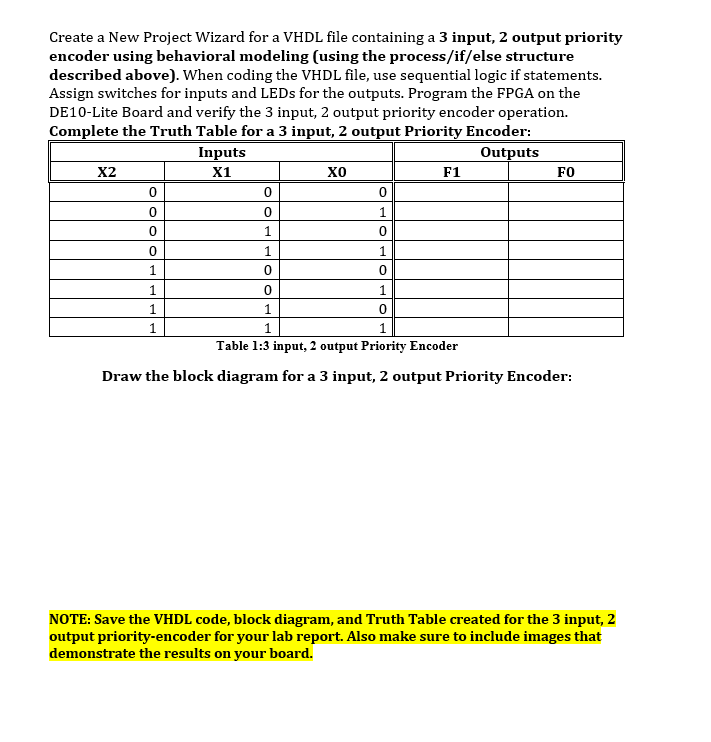
Write a VHDL code file that uses a 3 input 2 output encoder. draw a block diagram to go along with the VHDL code and complete the truth table.
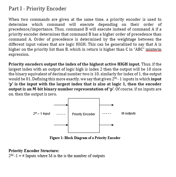
Part 1 - Priority Encoder When two commands are given at the same time, a priority encoder is used to determine which command will execute depending on their order of precedence/importance. Thus, command B will execute instead of command A if a priority encoder determines that command B has a higher order of precedence than command A. Order of precedence is determined by the weightage between the different input values that are logic HIGH. This can be generalized to say that A is higher on the priority list than B, which in return is higher than C in "ABC" minterm expression. Priority encoders output the index of the highest active HIGH input. Thus, if the largest index with an output of logic high is index 2 then the output will be 10 since the binary equivalent of decimal number two is 10, similarly for index of 1, the output would be 01. Defining this more exactly, we say that given 2M- 1 inputs in which input 'p' is the input with the largest index that is also at logic 1, then the encoder output is an M-bit binary number representation of 'p'. Of course, if no inputs are on, then the output is zero. 2M-1 Input Priority Encoder Moutputs Figure l: Block Diagram of a Priority Encoder Priority Encoder Structure: 2M-1 = # Inputs where M is the is the number of outputs Create a New Project Wizard for a VHDL file containing a 3 input, 2 output priority encoder using behavioral modeling (using the process/if/else structure described above). When coding the VHDL file, use sequential logic if statements. Assign switches for inputs and LEDs for the outputs. Program the FPGA on the DE10-Lite Board and verify the 3 input, 2 output priority encoder operation. Complete the Truth Table for a 3 input, 2 output Priority Encoder: Inputs Outputs X2 X1 0 F1 FO 0 0 0 1 0 1 0 1 1 1 0 0 1 1 1 1 0 1 1 0 1 Table 1:3 input, 2 output Priority Encoder Draw the block diagram for a 3 input, 2 output Priority Encoder: NOTE: Save the VHDL code, block diagram, and Truth Table created for the 3 input, 2 output priority-encoder for your lab report. Also make sure to include images that demonstrate the results on your boardStep by Step Solution
There are 3 Steps involved in it
Step: 1

Get Instant Access to Expert-Tailored Solutions
See step-by-step solutions with expert insights and AI powered tools for academic success
Step: 2

Step: 3

Ace Your Homework with AI
Get the answers you need in no time with our AI-driven, step-by-step assistance
Get Started


