Question
Write a VHDL description that has: an std_logic clock input, an active-low std_logic reset input whose name ends with the letter n (e.g. reset_n or
Write a VHDL description that has:
-
an std_logic clock input,
-
an active-low std_logic reset input whose name ends with the letter n (e.g. reset_n or RSTN),
-
a 4-bit std_logic_vector output
Your design should operate as follows:
-
The output should change only on the rising edge of the clock.
-
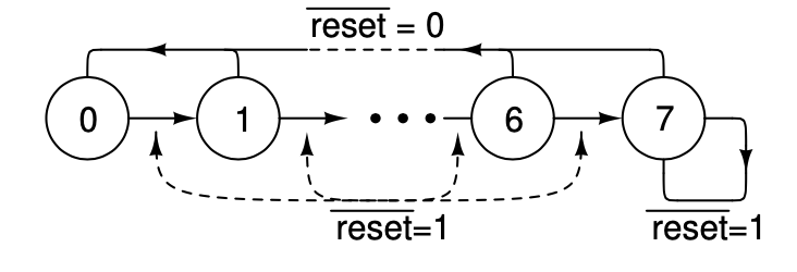
If the reset input is asserted (i.e. low) at the rising edge of the clock then the first digit of your student number should be displayed in binary on the led outputs.
-
If the reset input is not asserted at the rising edge of the clock then the next digit of your student number should be displayed. Your design should not advance past the last digit.
Draw the state transition diagram and write VHDL source code for your counter and bring hard-copies to the lab.
Your state transition table should have conditions on each transition:
-

Note that since your student number could have duplicates of the same digit, your states should not be the displayed values. Instead, the state should be the digit position being displayed (0 through 7). Use a selected assignment to convert from the digit position to the displayed digit value.
As in the previous lab, youll need to debounce the clock switch input. In your VHDL file include:
-- before the architecture: use work.debounce_pkg.all ;
-- within the architecture: debounce1: debounce port map ( clk_in, clk ) ;
where clk_in and clk are the signal names you used for the un-debounced and debounced clock signals respectively.
The use clause will make the debounce component available. The component instantiation statement will include an instance of the debounce component in your design, name the instance debounce1, and connect clk_in to the debounce components input port and clk to its output port (assuming you have signals with these names).
Hints
Draw a block diagram of your design before you begin coding. For this lab it might be:

where block 1) computes the next digit position based on the value of the current digit position and the reset input (e.g. using a conditional assignment); block 2) stores the current digit position value (e.g. by creating a register); and block 3) computes the output digit value based on the current digit position (e.g. by using a selected assignment).
-
Declare signals within the architecture for the current and next digit values (e.g. dig, dig_next) and use a conditional assignment to set the value of the next digit based on the current digit. The internal signal declarations are placed just before the architectures begin keyword.
-
You will also need to declare an internal signal within the architecture for the debounced clock (the clock declared in the entitys port is the un- debounced signal).
-
You can use hexadecimal literals x "5" instead of binary ones ("0101")
The stdent number is "11843836
reset = 0 0- 000 reset=1 reset=1 next digit digit led reset D clock a reset = 0 0- 000 reset=1 reset=1 next digit digit led reset D clock aStep by Step Solution
There are 3 Steps involved in it
Step: 1

Get Instant Access to Expert-Tailored Solutions
See step-by-step solutions with expert insights and AI powered tools for academic success
Step: 2

Step: 3

Ace Your Homework with AI
Get the answers you need in no time with our AI-driven, step-by-step assistance
Get Started


