Answered step by step
Verified Expert Solution
Question
1 Approved Answer
write the discuss please Introduction: Pad/see + b) (Ls + R + The structure of the control system has the form shown in the figure


write the discuss please
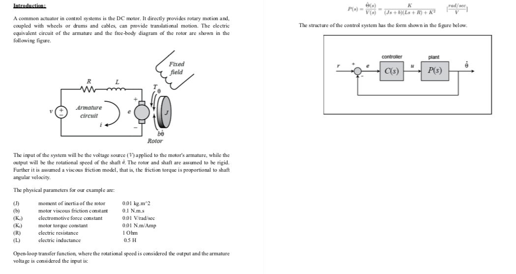
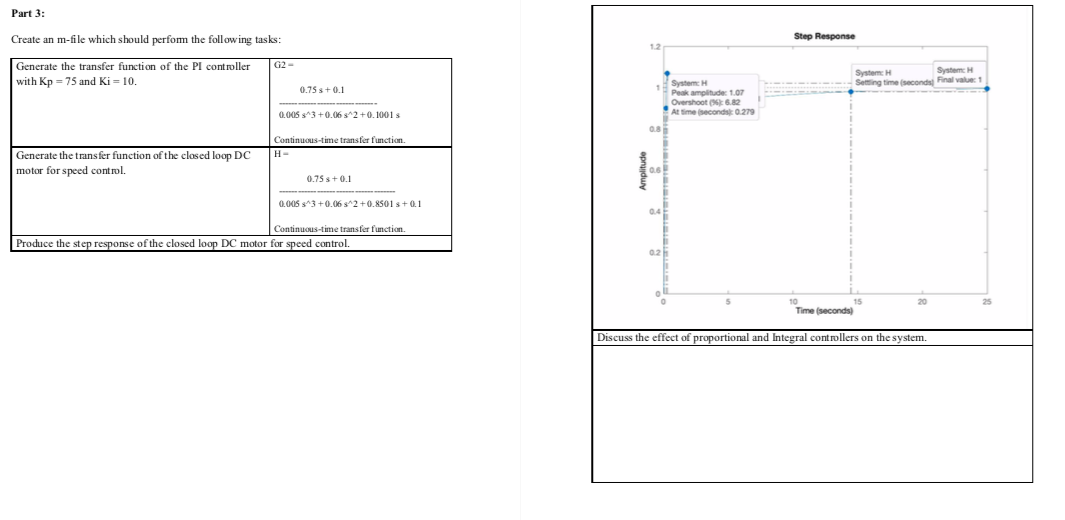
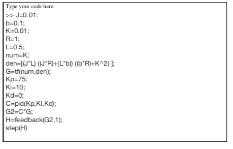
Introduction: Pad/see + b) (Ls + R + The structure of the control system has the form shown in the figure below. A common actuator in control systems is the DC motor. It directly provides rotary motion and, coupled with wheels or drums and cables, can provide translational motion. The electric equivalent circuit of the armature and the free-body diagram of the rotor are shown in the following figure. controller plant Fixed field C(s) P(S) RL M Armature circuit Rotor The input of the system will be the voltage source (V) applied to the motor's armature, while the output will be the rotational speed of the shaft . The rotor and shaft are assumed to be rigid. Further it is assumed a viscous friction model, that is, the friction torque is proportional to shaft angular velocity. The physical parameters for our example are: (J) (K.) (K) (R) moment of inertia of the rotor motor viscous friction constant electromotive force constant motor torque constant electric resistance electric inductance 0.01 kg.m2 0.1 N.m.s 0.01 V/rad/sec 0.01 N.m/Amp 1 Ohm 0.5 H Open-loop transfer function, where the rotational speed is considered the output and the armature voltage is considered the input is: Part 3: Create an m-file which should perfom the following tasks: Step Response G2- Generate the transfer function of the PI controller with Kp = 75 and Ki = 10. System Sering time second System Final value: 1 0.75 +0.1 System Peak amplitude: 107 Overshoot 6.82 At time second 0279 0.005 3^3 +0.06 s^2 +0.1001 Continuous-time transfer function Generate the transfer function of the closed loop DC motor for speed control. Amplitude 0.75 s + 0.1 0.005 313 +0.06 s^2 +0.8501 s + 0.1 Continuous-time transfer function. Produce the step response of the closed loop DC motor for speed control. 15 Time (seconds) Discuss the effect of proportional and Integral controllers on the system. Type your code here: >> J=0.01; b=0.1; K=0.01; R=1; L=0.5; num=K; den=[(J'L) ((JR)+(L*b)) ((b*R)+K^2) }; G=tf(num,den); Kp=75; Ki=10; Kd=0; C=pid(Kp, Ki,Kd); G2=C"G; H=feedback (G2,1); step(H)Step by Step Solution
There are 3 Steps involved in it
Step: 1

Get Instant Access to Expert-Tailored Solutions
See step-by-step solutions with expert insights and AI powered tools for academic success
Step: 2

Step: 3

Ace Your Homework with AI
Get the answers you need in no time with our AI-driven, step-by-step assistance
Get Started


