Answered step by step
Verified Expert Solution
Question
1 Approved Answer
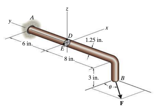
y. A Z D 1.25 in. 6 in. E 8 in. 3 in. x B F 8-47. The bent shaft is fixed in the


y. A Z D 1.25 in. 6 in. E 8 in. 3 in. x B F 8-47. The bent shaft is fixed in the wall at A. If a force F is applied at B, determine the stress components at points D and E. Show the results on a differential element located at each of these points. Take F= 12 lb and 0 =0. *8-48. The bent shaft is fixed in the wall at A. If a force F is applied at B, determine the stress components at points D and E. Show the results on a differential element located at each of these points. Take F= 12 lb and 0 = 90. 8-49. The bent shaft is fixed in the wall at A. If a force F is applied at B, determine the stress components at points D and E. Show the results on a volume element located at each of these points. Take F = 12 lb and 0 = 45.
Step by Step Solution
There are 3 Steps involved in it
Step: 1

Get Instant Access to Expert-Tailored Solutions
See step-by-step solutions with expert insights and AI powered tools for academic success
Step: 2

Step: 3

Ace Your Homework with AI
Get the answers you need in no time with our AI-driven, step-by-step assistance
Get Started


