Answered step by step
Verified Expert Solution
Question
1 Approved Answer
You are asked to design a circuit depicted in the black-box (block) diagram shown in Fig. 1. The circuit takes three (word-level) inputs A[1:0],B[1:0],I[1:0]; where
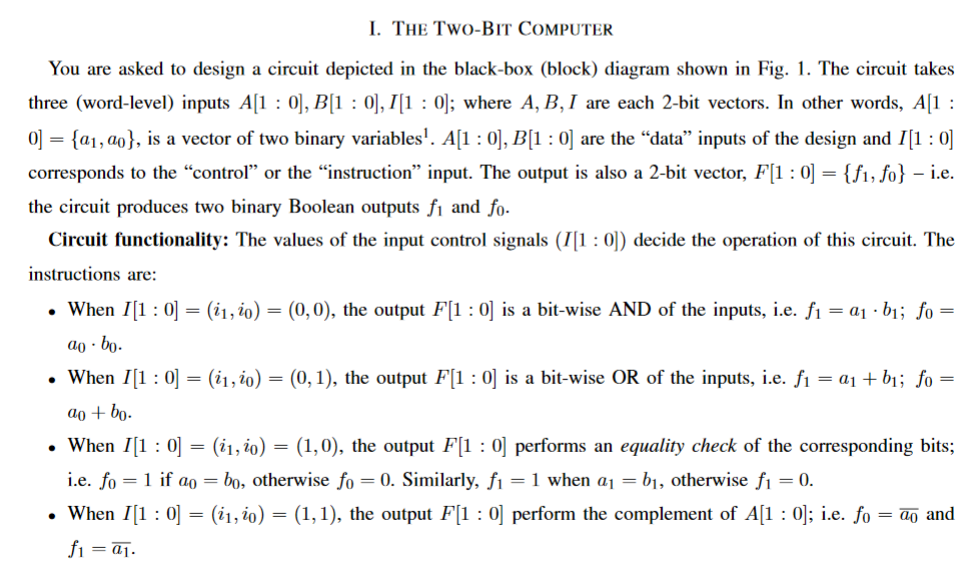
You are asked to design a circuit depicted in the black-box (block) diagram shown in Fig. 1. The circuit takes three (word-level) inputs A[1:0],B[1:0],I[1:0]; where A,B,I are each 2-bit vectors. In other words, A[1: 0]={a1,a0}, is a vector of two binary variables 1.A[1:0],B[1:0] are the "data" inputs of the design and I[1:0] corresponds to the "control" or the "instruction" input. The output is also a 2-bit vector, F[1:0]={f1,f0} - i.e. the circuit produces two binary Boolean outputs f1 and f0. Circuit functionality: The values of the input control signals (I[1:0]) decide the operation of this circuit. The instructions are: - When I[1:0]=(i1,i0)=(0,0), the output F[1:0] is a bit-wise AND of the inputs, i.e. f1=a1b1;f0= a0b0. - When I[1:0]=(i1,i0)=(0,1), the output F[1:0] is a bit-wise OR of the inputs, i.e. f1=a1+b1;f0= a0+b0. - When I[1:0]=(i1,i0)=(1,0), the output F[1:0] performs an equality check of the corresponding bits; i.e. f0=1 if a0=b0, otherwise f0=0. Similarly, f1=1 when a1=b1, otherwise f1=0. - When I[1:0]=(i1,i0)=(1,1), the output F[1:0] perform the complement of A[1:0]; i.e. f0=a0 and f1=a1
Step by Step Solution
There are 3 Steps involved in it
Step: 1
Get Instant Access to Expert-Tailored Solutions
See step-by-step solutions with expert insights and AI powered tools for academic success
Step: 2
Step: 3
Ace Your Homework with AI
Get the answers you need in no time with our AI-driven, step-by-step assistance
Get Started