Question
You are assigned the task of designing and building a radiation safety interlock system for a new medical imaging apparatus. The problem is that the
You are assigned the task of designing and building a radiation safety interlock system for a new medical imaging apparatus. The problem is that the device releases sufficient radiation that it is not safe for health workers to be repeated exposed when the device is in operation.
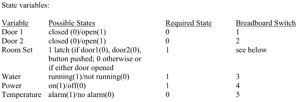
The apparatus is located in a room with two doors, one where the patient enters, and the second leading to a control room. After the patient enters the room and is properly positioned, both doors must be closed and the operator located in the control room. On entering the control room and checking through a window that the imaging room is clear of unauthorized individuals, the operator pushes a Room Set button that enables the imaging device if and only if both doors are already in the closed state. The Room Set enable is lost if either door is subsequently opened. To beoperated safely, the imaging device needs to have a continuous water flow and a 30A current flow. The device has a thermocouple interlock that goes high when the water temperature rises about 35C.
Use the switches on your breadboard to simulate each of the variables OTHER than the Room Set switch, as indicated in the table. A momentary contact switch should be used for the Room Set operation. Build the logic circuit so that the output is high (1) if operation of imaging device is safe. If the output goes low (0) the SuperX automatically shuts off.
For your worksheet, you need to turn in a detailed circuit diagram and truth tables verifying the operation at each stage. You must show the TA or instructor that your circuit performs to specifications.

Step by Step Solution
There are 3 Steps involved in it
Step: 1

Get Instant Access to Expert-Tailored Solutions
See step-by-step solutions with expert insights and AI powered tools for academic success
Step: 2

Step: 3

Ace Your Homework with AI
Get the answers you need in no time with our AI-driven, step-by-step assistance
Get Started


