Answered step by step
Verified Expert Solution
Question
1 Approved Answer
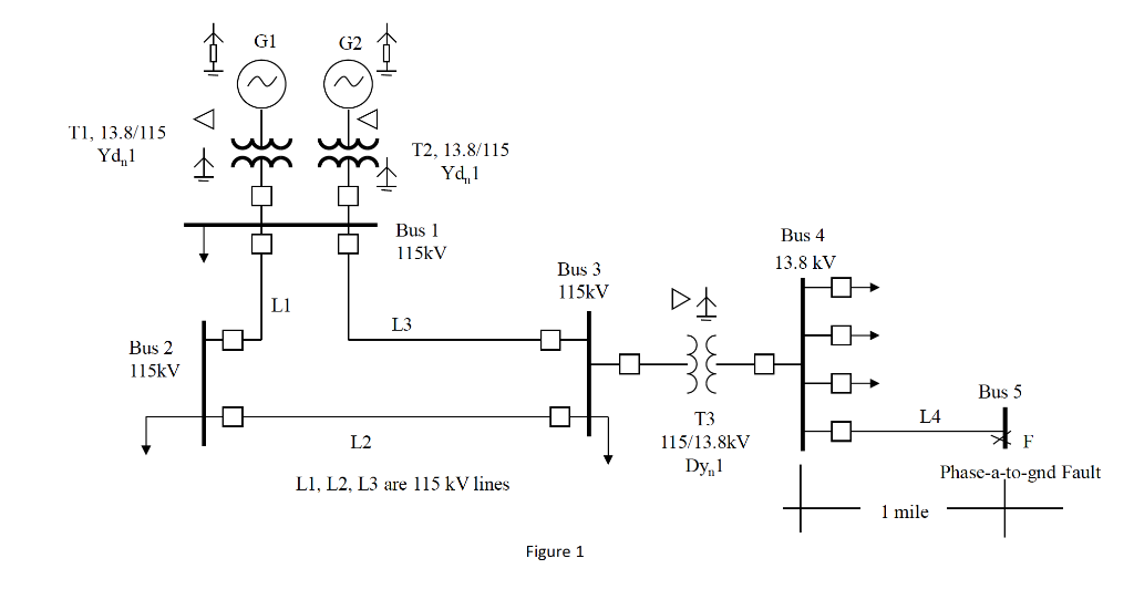
You are in charge of calculating a single-phase-to-ground fault at the point indicated in the system shown in Figure 1. Your first task is


You are in charge of calculating a single-phase-to-ground fault at the point indicated in the system shown in Figure 1. Your first task is to draw the sequence networks and connect them considering the type of fault you are going to analyze. Draw the sequence networks and connect them showing the impedances of each of the system's elements. Draw the impedance as rectangles (as done in class) without giving any numerical values. Use a separate sheet of paper to present your drawing. Do not include the phase shifters for the delta-wye transformers. (It does not have to be beautiful, but it has to be clear --as being drawn by an engineering student.) T1, 13.8/115 Yd, 1 Bus 2 115kV foli VA G1 L1 G2 L2 foli T2, 13.8/115 Yd,1 Bus 1 115kV L3 L1, L2, L3 are 115 kV lines Bus 3 115kV Figure 1 T3 115/13.8kV Dy 1 Bus 4 13.8 kV L4 mile Bus 5 F Phase-a-to-gnd Fault
Step by Step Solution
★★★★★
3.38 Rating (167 Votes )
There are 3 Steps involved in it
Step: 1

Get Instant Access to Expert-Tailored Solutions
See step-by-step solutions with expert insights and AI powered tools for academic success
Step: 2

Step: 3

Ace Your Homework with AI
Get the answers you need in no time with our AI-driven, step-by-step assistance
Get Started


