

Question: You are required to design a digital alarm clock using the Rx 6 3 N development board and the plug in daughter board. The alarm
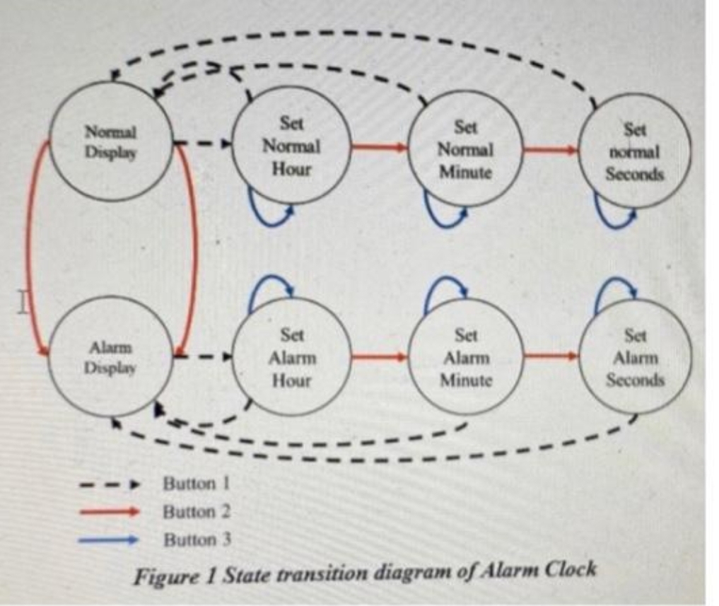
You are required to design a digital alarm clock using the RxN development board and the plug in daughter board. The alarm clock's functionality follows the State Transition Diagram in Figure As there are no audible outputs on these boards, use two LEDs that flash alternately to signify an alarm condition. Use a third LED to give a visual output as to when the alarm is in a set condition. The alarm clock uses three buttons to change the mode of operation, as indicated in State Transition Diagram The alarm clocks alarm can only be set or cleared in the "Normal Display state, this is the only state that the alarm condition can be activated, which would require the alarm to be set and the actual time to match the alarm time. If the alarm has been activated then any of the three buttons will stop the alarm, taking it out of the set condition. If the alarm is not stopped by user interaction, then after one minute the alarm clock will automatically stop the LED toggling, again taking it out of a set condition You also need to ensure that there is timeout facilities for when the user takes the application into a state other than Normal Display. This would ensure that after a period of time with no user interaction the application would revert back to the 'Normal Display state. This feature is not indicated on the State Transition Diagram. Figure but needs to be included and submitted as part of your report Normal Display Set Normal Hour Set Normal Minute Set normal Seconds Alarm Display Set Alarm Hour Set Alarm Set Alarm Seconds Minute Button! Button Button Figure State transition diagram of Alarm Clock
Figure State transition diagram of Alarm Clock
Step by Step Solution
There are 3 Steps involved in it
1 Expert Approved Answer
Step: 1 Unlock

Question Has Been Solved by an Expert!
Get step-by-step solutions from verified subject matter experts
Step: 2 Unlock
Step: 3 Unlock