Question
You are required to design an embedded system to control a machinery on a factor floor. The system will take inputs via 3 switches S1-S3.
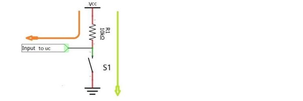
You are required to design an embedded system to control a machinery on a factor floor. The system will take inputs via 3 switches S1-S3. Each Switch is connected as follows to the microcontrollers GPIO port as shown below (eg: S1). (You may choose the ports as desired.)
After power up, the system will wait for it to be enabled via switch S1. The purpose of the switches is shown in the diagram below. Only 1 of the pins from S2/S3 will be closed at a time. S1: System enabled if switch is closed S2: If S1 is Closed, and S2 is closed, an output of 20Khz, 50% duty cycle is generated at one of the pins of microcontroller which is connected to the machinery to be controlled (Say Pin X of the machine to be controlled). S3: If S1 is Closed, and S3 is closed, an output of 20Khz,75% duty cycle is generated at one of the pins of microcontroller which is connected to the machinery to be controlled (Say Pin X of the machine to be controlled). Note: Marks will be awarded based on the optimal configuration of each peripheral as per the requirement and accuracy. Indicate assumptions if any. Assume that SYSCLK is configured to xxMhz. Other clocks can be selected as required to serve the application. (a) Show the clock configuration of peripheral buses required to serve the application. Only the prescalar values used and the peripheral bus frequencies are required to be mentioned (b) Show the configuration of on-chip peripherals required to serve the application. Configuration should be done in the right order. Every peripheral including NVIC(used if any should be explained) . The correct registers of microcontroller should be indicated. Eg: To configure the baud rate configure UART_BRR register to a value of 0x1117 UART_BRR=0X1117. (c) Also indicate the activities that will be completed when each switch is pressed via Embedded C code or pseudocode. The correct registers of microcontroller should be indicated.
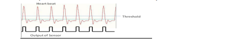
Q1. An intelligent patient Care System You are assigned to design some of the modules required for patient care in a Hospital. Technical Specifications: Patient Monitoring System The system is to be deployed in a hospital ward that can accommodate around 8 patients. The system has two subunits a) Bedside unit b) Master Control Unit. The bedside unit will obtain certain vital body parameters like heart rate, blood pressure, and body temperature from the sensors placed on the patient at an interval of 1 minute. The bed-side unit will verify whether the measured parameters are within the safe limits. The limits, i.e. the maximum and minimum values of each body parameter can be configured by the expert using a front panel available with the bedside unit. (Front panel design need not be done]. The 8-bed site units are interfaced to the Master control unit via an asynchronous serial bus. The functionality of the bedside unit may be modified in the future, so it is required that all the bedside units can communicate with each other over the bus. The bedside unit reads the data from the following sensors: a) Body temperature Sensor: The sensor produces a conditioned analog voltage of range 0-3.3V. The resolution of the sensor is .0035V. A High-to low pulse has to be provided to the sensor to update the temperature reading and once the data is ready, it generates a high-to-low pulse on one of its output pins. The temperature data is read out at an interval of 1minute from the sensor ( 1minute interval would be sufficient as body temperature is not expected to increase rapidly) b) Blood Pressure Sensor: The sensor output is 8-bit serial data via UART protocol. Odd parity and 1 stop bit is enabled . The sensor has to be configured via a UART write command. Following this the sensor will provide data at an interval of 30second. Supported baud rate for communication is 115200 baud. c) Heartbeat sensor: The sensor provides a high pulse for every heartbeat. The sensor senses the heartbeat signal applies a threshold to the signal (As shown in the figure) and for every heartbeat, the sensor produces a pulse. The count of the pulses can be used to obtain BPM or beats per minute. [The maximum and minimum limit is in terms of BPM ] The data from the body temperature sensor and blood pressure sensor has to be read out by the bedside unit at an interval of 1 minute. Data from the three sensors will be read by the bedside unit and then compared with the limit set by the user (minimum and maximum) and in case of any abnormality is detected, a packet frame with the measured parameters and bed number and instant of time at which the value is recorded will be transmitted to the master control unit. The maximum expected data rate is around 1Mbps. The Master control unit should also be able to request the data from a particular bedside unit if required. The master control unit can then transfer the data via the Ethernet interface or GPRS interface to raise an alert to the concerned medical practitioners. The master control unit need not be designed. Only the interface between the master control unit and the bedside unit needs to be shown The bedside unit is line-powered. Note: Marks will be awarded based on the optimal configuration of each peripheral as per the requirement. Indicate assumptions if any. Assume that the system clock and AHB bus are set to 100Mhz and APB1 and APB2 clock is set to 25Mhz. (d) Assume that system is already configured via the front panel. Describe the functional description of the data collection module (DCM) of the bedside unit. The input to the DCM module is an enable signal. If enable signal is high, the module should collect data from the three sensors (body temperature, blood pressure, and Heart rate sensor) and check if the value is within limits. The output from the data collection unit is activated only when there is an anomaly. [3M] (e) How many interrupts will be utilized for this system design? What are the priorities of the interrupts? Mention the major activates to be carried out within each interrupt service routine [3M] (f) Show the configuration of on-chip peripherals required for the heart-beat monitoring. [3M] (g) Show the UART configuration (including interrupts if required) . How would you estimate if the baud rate you have set for the microcontroller UART peripheral is within the allowable tolerance in the variation of baud rate so that the microcontroller can receive data correctly?
Step by Step Solution
There are 3 Steps involved in it
Step: 1

Get Instant Access to Expert-Tailored Solutions
See step-by-step solutions with expert insights and AI powered tools for academic success
Step: 2

Step: 3
Ace Your Homework with AI
Get the answers you need in no time with our AI-driven, step-by-step assistance
Get Started