Answered step by step
Verified Expert Solution
Question
1 Approved Answer
You are required to produce an Aspen HYSYS flow sheet of an LPG treating process using tertiary alkanolamine (methyldiethanolamine; MDEA) as shown in the


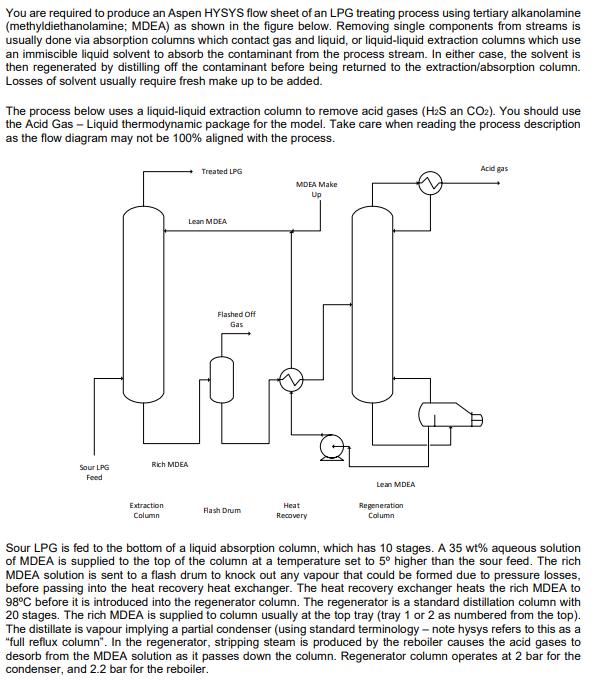
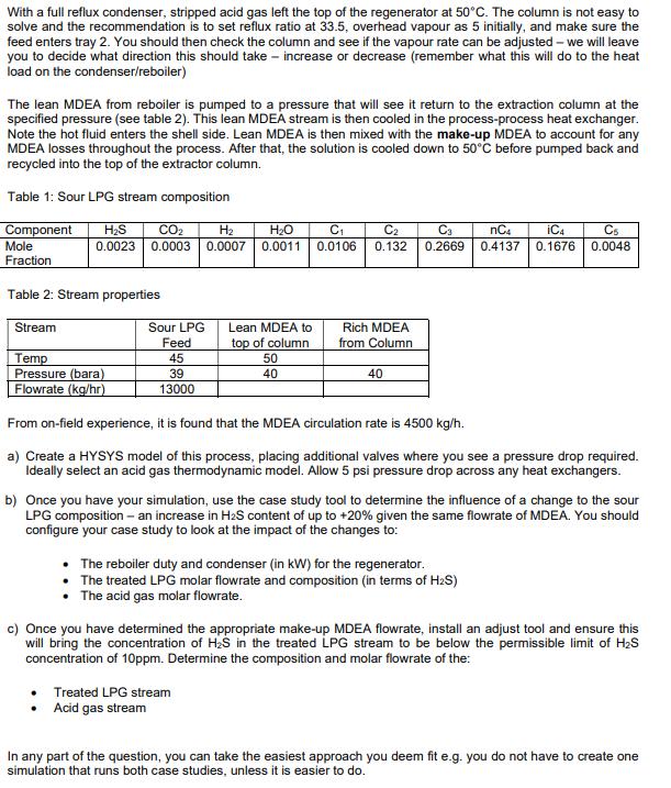
You are required to produce an Aspen HYSYS flow sheet of an LPG treating process using tertiary alkanolamine (methyldiethanolamine; MDEA) as shown in the figure below. Removing single components from streams is usually done via absorption columns which contact gas and liquid, or liquid-liquid extraction columns which use an immiscible liquid solvent to absorb the contaminant from the process stream. In either case, the solvent is then regenerated by distilling off the contaminant before being returned to the extraction/absorption column. Losses of solvent usually require fresh make up to be added. The process below uses a liquid-liquid extraction column to remove acid gases (H2S an CO2). You should use the Acid Gas - Liquid thermodynamic package for the model. Take care when reading the process description as the flow diagram may not be 100% aligned with the process. Rich MDEA Sour LPG Feed Treated LPG Lean MDEA Flashed Off Gas MDEA Make Up Extraction Column Flash Drum Heat Recovery Lean MDEA Regeneration Column Acid gas Sour LPG is fed to the bottom of a liquid absorption column, which has 10 stages. A 35 wt% aqueous solution of MDEA is supplied to the top of the column at a temperature set to 5 higher than the sour feed. The rich MDEA solution is sent to a flash drum to knock out any vapour that could be formed due to pressure losses, before passing into the heat recovery heat exchanger. The heat recovery exchanger heats the rich MDEA to 98C before it is introduced into the regenerator column. The regenerator is a standard distillation column with 20 stages. The rich MDEA is supplied to column usually at the top tray (tray 1 or 2 as numbered from the top). The distillate is vapour implying a partial condenser (using standard terminology - note hysys refers to this as a "full reflux column". In the regenerator, stripping steam is produced by the reboiler causes the acid gases to desorb from the MDEA solution as it passes down the column. Regenerator column operates at 2 bar for the condenser, and 2.2 bar for the reboiler. With a full reflux condenser, stripped acid gas left the top of the regenerator at 50C. The column is not easy to solve and the recommendation is to set reflux ratio at 33.5, overhead vapour as 5 initially, and make sure the feed enters tray 2. You should then check the column and see if the vapour rate can be adjusted - we will leave you to decide what direction this should take - increase or decrease (remember what this will do to the heat load on the condenser/reboiler) The lean MDEA from reboiler is pumped to a pressure that will see it return to the extraction column at the specified pressure (see table 2). This lean MDEA stream is then cooled in the process-process heat exchanger. Note the hot fluid enters the shell side. Lean MDEA is then mixed with the make-up MDEA to account for any MDEA losses throughout the process. After that, the solution is cooled down to 50C before pumped back and recycled into the top of the extractor column. Table 1: Sour LPG stream composition Component Mole HS CO2 H 0.0023 0.0003 0.0007 HO 0.0011 C 0.0106 C2 0.132 Ca 0.2669 nC4 0.4137 iC4 C5 0.1676 0.0048 Fraction Table 2: Stream properties Stream Sour LPG Feed Lean MDEA to top of column Rich MDEA from Column Temp 45 50 Pressure (bara) 39 40 40 Flowrate (kg/hr) 13000 From on-field experience, it is found that the MDEA circulation rate is 4500 kg/h. a) Create a HYSYS model of this process, placing additional valves where you see a pressure drop required. Ideally select an acid gas thermodynamic model. Allow 5 psi pressure drop across any heat exchangers. b) Once you have your simulation, use the case study tool to determine the influence of a change to the sour LPG composition - an increase in H2S content of up to +20% given the same flowrate of MDEA. You should configure your case study to look at the impact of the changes to: The reboiler duty and condenser (in kW) for the regenerator. The treated LPG molar flowrate and composition (in terms of H2S) The acid gas molar flowrate. c) Once you have determined the appropriate make-up MDEA flowrate, install an adjust tool and ensure this will bring the concentration of H2S in the treated LPG stream to be below the permissible limit of HS concentration of 10ppm. Determine the composition and molar flowrate of the: Treated LPG stream Acid gas stream In any part of the question, you can take the easiest approach you deem fit e.g. you do not have to create one simulation that runs both case studies, unless it is easier to do.
Step by Step Solution
There are 3 Steps involved in it
Step: 1

Get Instant Access to Expert-Tailored Solutions
See step-by-step solutions with expert insights and AI powered tools for academic success
Step: 2

Step: 3

Ace Your Homework with AI
Get the answers you need in no time with our AI-driven, step-by-step assistance
Get Started


