Answered step by step
Verified Expert Solution
Question
1 Approved Answer
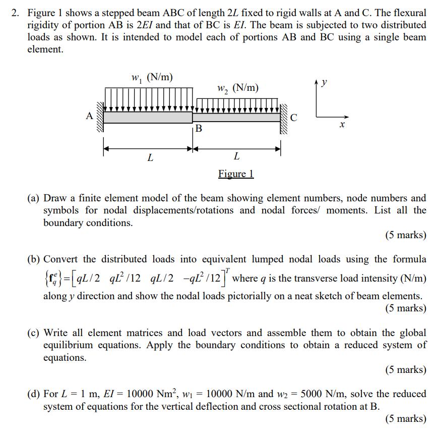
2. Figure 1 shows a stepped beam ABC of length 2L fixed to rigid walls at A and C. The flexural rigidity of portion

2. Figure 1 shows a stepped beam ABC of length 2L fixed to rigid walls at A and C. The flexural rigidity of portion AB is 2EI and that of BC is EI. The beam is subjected to two distributed loads as shown. It is intended to model each of portions AB and BC using a single beam element. A www. w (N/m) L B W (N/m) L Figure 1 C y X (a) Draw a finite element model of the beam showing element numbers, node numbers and symbols for nodal displacements/rotations and nodal forces/ moments. List all the boundary conditions. (5 marks) (b) Convert the distributed loads into equivalent lumped nodal loads using the formula {}=[qL/2_qL/12_qL/2 -q1/12] where q is the transverse load intensity (N/m) along y direction and show the nodal loads pictorially on a neat sketch of beam elements. (5 marks) (c) Write all element matrices and load vectors and assemble them to obtain the global equilibrium equations. Apply the boundary conditions to obtain a reduced system of equations. (5 marks) = (d) For L = 1 m, EI = 10000 Nm, wi 10000 N/m and w2 = 5000 N/m, solve the reduced system of equations for the vertical deflection and cross sectional rotation at B. (5 marks)
Step by Step Solution
★★★★★
3.30 Rating (162 Votes )
There are 3 Steps involved in it
Step: 1

Get Instant Access to Expert-Tailored Solutions
See step-by-step solutions with expert insights and AI powered tools for academic success
Step: 2

Step: 3

Ace Your Homework with AI
Get the answers you need in no time with our AI-driven, step-by-step assistance
Get Started


