Answered step by step
Verified Expert Solution
Question
1 Approved Answer
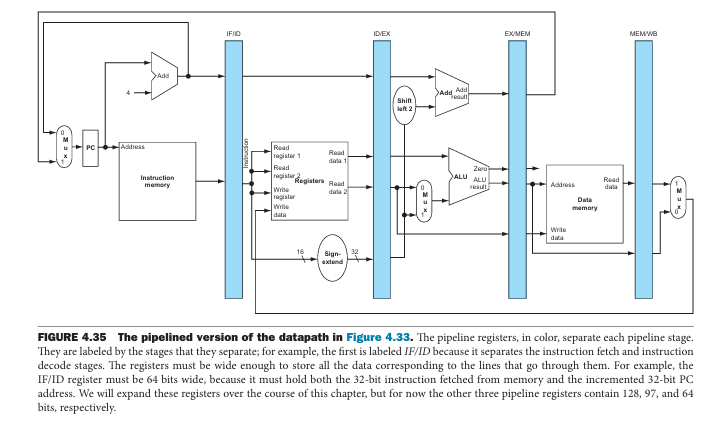
You should write your answers as clearly and concisely as possible. For each instruction, use figure 4 . 3 5 and add the control signals
You should write your answers as clearly and concisely as possible. For each instruction,
use figure and add the control signals as shown in figure To keep the resulting
figure simple, just add the control signals that are relevant to the instruction in each
problem. One copy of figure for each instruction should be sufficient. points each
Write your name and homework number on the top of the first page.
Implement the li Itype instruction on the multicycle datapath. Include your diagram,
a description, and the control signal values.
Implement the lui Itype instruction on the datapath. Include your diagram, a
description, and the control signal values.
Implement the jal Jtype instruction on the multicycle datapath. Include your
diagram, a description, and the control signal values.
Implement the jr Rtype instruction on the multicycle datapath. Include your
diagram, a description, and the control signal values FIGURE The pipelined version of the datapath in Figure The pipeline registers, in color, separate each pipeline stage.
They are labeled by the stages that they separate; for example, the first is labeled IFID because it separates the instruction fetch and instruction
decode stages. The registers must be wide enough to store all the data corresponding to the lines that go through them. For example, the
IFID register must be bits wide, because it must hold both the bit instruction fetched from memory and the incremented bit PC
address. We will expand these registers over the course of this chapter, but for now the other three pipeline registers contain and
bits, respectively. FIGURE The control lines for the final three stages. Note that four of the nine control lines
are used in the EX phase, with the remaining five control lines passed on to the EXMEM pipeline register
extended to hold the control lines; three are used during the MEM stage, and the last two are passed to MEM
WB for use in the WB stage.

Step by Step Solution
There are 3 Steps involved in it
Step: 1

Get Instant Access to Expert-Tailored Solutions
See step-by-step solutions with expert insights and AI powered tools for academic success
Step: 2

Step: 3

Ace Your Homework with AI
Get the answers you need in no time with our AI-driven, step-by-step assistance
Get Started


