Question
you will be building a 1-bit Full Adder circuit. a. Use a K-map to minimize Cout (Sum would be requested too, but it doesn't
you will be building a 1-bit Full Adder circuit.
a. Use a K-map to minimize Cout (Sum would be requested too, but it doesn't simplify further, so just Cout).
b. In digital,start with 3 input components, "A", "B", and "Cin", and 2 output components, "Sum" and "Cout".
c. Implement a Full adder using any method you would like, but you cannot use the Adder component .
(1)Think a little about which method you want to use. You can either use the SOP from the truth table to make the schematic, or use the XOR you made in the previous lab.
(2) Note: If you make the schematic from SOP, because this table has 2 outputs, you essentially need to make two circuits in one. For doing Sum, ignore Cout and implement Sum in terms of A, B, and Cin. For doing Cout, ignore Sum and implement Cout in terms of A, B, and Cin (but remember to use a K-map to simplify Cout and make the schematic from the simplified form).
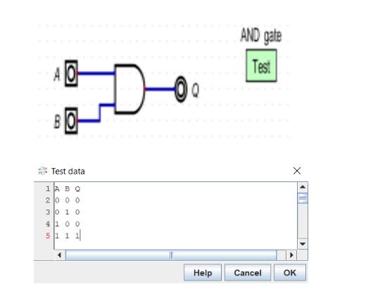
(3) To test your adder, you can also go to components ---> misc ---> test case. Put the test case in your file. Right click it, go to edit, and put in what the inputs and outputs would be. So, for example, this is how you could test the schematic for an AND gate:

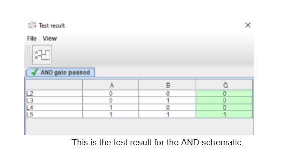
Once you put in the inputs and outputs, go to simulation → run tests, and make sure everything passes. To test your adder, do the process for the adder truth table.
If everything passes, your output will be shown in green like this:

Task 2: Adder/Subtractor
For this task, you will be creating an Adder/Subtractor, which can toggle between which of the two operations it is doing. Essentially, take the adder that you made in task 1, confirm that it works and take screenshots as needed for submission purposes, and then add the subtraction functionality to it.
Consider the fact that you have an existing component which can do 4-bit addition, and suppose that you want to be able to do, A - B for some numbers A and B. Using what you've learned about Two's Complement, you should know that A-B is the same as A + (-B).In Two's complement, -B is the result of inverting B, and adding 1. In order to invert B, you can't just use NOT gates, because you need to be able to turn on/off the inversion(since you want to use the same circuit for both addition and subtraction). In order to be able to toggle between inverting B(while subtracting) and using B as it is (while adding), you will need a component that works like the table below:
| INV | A | Q |
| 0 | 0 | 0 |
| 0 | 1 | 1 |
| 1 | 0 | 1 |
| 1 | 1 | 0 |
When INV is 0, then Q just outputs whatever A is and when INV is 1, then Q outputs NOT A, which you should be able to see from the table. This table should be familiar to you as it exactly looks like the table for an XOR gate. As a result, if you pass in one of your inputs(B) as one of the inputs to an XOR gate, and use the other to control whether or not you are inverting, you can toggle whether you are adding or subtracting.
In order to do the extra +1 for Two's complement, you can just set Cin to 1. Otherwise, it should just be 0 by default, because you don't want to carry anything into the adder when adding. Ultimately, your circuit should perform A + B when the SUB input is 0, and A + ~B + 1, with ~B being the inverse of B, and the +1 coming from Cin.
What needs to be done:
1. The schematic for your adder, including proof that it works properly (via truth tables or tests), and that the simulation runs without errors. Also, provide an explanation of how you came up with your schematic.
2. The SOP from the truth table, and the simplified form of Cout and Sum using a K-map.
3. The schematic for your adder/subtractor, including proof that it works properly (via truth tables or tests), and that the simulation runs without errors. Also, provide an explanation of how you came up with your schematic and what the difference was between this and the regular adder. That is, what else did you need to add to make it do subtraction as well?
Test data 1 AB Q 2000 30 10 4 1 0 0 51 1 1 AND gate Test Help Cancel OK
Step by Step Solution
There are 3 Steps involved in it
Step: 1

Get Instant Access to Expert-Tailored Solutions
See step-by-step solutions with expert insights and AI powered tools for academic success
Step: 2

Step: 3

Ace Your Homework with AI
Get the answers you need in no time with our AI-driven, step-by-step assistance
Get Started


