Answered step by step
Verified Expert Solution
Question
1 Approved Answer
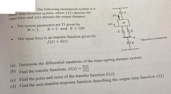
The following mechanical system is a linear time-invariant system, where f(t) denotes the input force and x(t) denotes the output distance. . The system


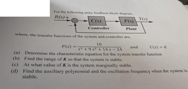
The following mechanical system is a linear time-invariant system, where f(t) denotes the input force and x(t) denotes the output distance. . The system parameters are TI given by M = 1, B = 5 and K = 100 . The input force is an impulse function given by f(t) = 8(t) x(1) f(0) M K K B Massless connector (a) Determine the differential equations of the mass-spring-damper system (b) Find the transfer functions G(s) = X(s) F(s) (c) Find the poles and zeros of the transfer function G(s) (d) Find the unit-impulse response function describing the output time function x(t) For the following unity feedback block diagram, R(s) + P(s) C(s) Controller P(s) = Plant where, the transfer functions of the system and controller are, 10 Y(s) and C(s) = K S3 +95 +14s-24 (a) Determine the characteristic equation for the system transfer function (b) Find the range of K so that the system is stable. (c) At what value of K is the system marginally stable. (d) Find the auxiliary polynomial and the oscillation frequency when the system is stable. The following mechanical system is a linear time-invariant system, where f(t) denotes the input force and x(t) denotes the output distance. . The system parameters are TI given by M = 1, B = 5 and K = 100 . The input force is an impulse function given by f(t) = 8(t) x(1) f(0) M K K B Massless connector (a) Determine the differential equations of the mass-spring-damper system (b) Find the transfer functions G(s) = x(s) F(s) (c) Find the poles and zeros of the transfer function G(s) (d) Find the unit-impulse response function describing the output time function x(t) For the following unity feedback block diagram, R(s) + P(s) C(s) Controller P(s) = Plant where, the transfer functions of the system and controller are, 10 Y(s) and C(s) = K S3 +95 +14s-24 (a) Determine the characteristic equation for the system transfer function (b) Find the range of K so that the system is stable. (c) At what value of K is the system marginally stable. (d) Find the auxiliary polynomial and the oscillation frequency when the system is stable.
Step by Step Solution
★★★★★
3.39 Rating (158 Votes )
There are 3 Steps involved in it
Step: 1
a To determine the differential equations of the massspringdamper system we can use Newtons second l...
Get Instant Access to Expert-Tailored Solutions
See step-by-step solutions with expert insights and AI powered tools for academic success
Step: 2

Step: 3

Ace Your Homework with AI
Get the answers you need in no time with our AI-driven, step-by-step assistance
Get Started


