Question
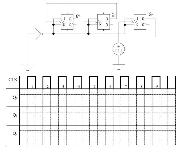
The following figure represents a sequential circuit. This circuit is built with 3 JK flip-flops to perform a specific function. The initial value of each
The following figure represents a sequential circuit. This circuit is built with 3 JK flip-flops to perform a specific function. The initial value of each rocker, before the first clock pulse, is "0".
1/ Give the states of the flip-flops for the first 9 clock pulses. Complete the waveforms (i.e. timing diagram) below.
2/ Give the diagram of the states of the circuit
3/ Explain the function performed by this circuit.
4/ Add to the circuit the logic gate necessary to reset the flip-flops (Q0 = 0, Q1 = 0, Q2 = 0), with the asynchronous entry CLEAR when the value of the three flip-flops reaches 101 (Q2 = 1 and Q1 = 0, and Q0 = 1)
CLK Q2 1 2 2 3 Q2 Ja Ka 5 Q NNNNNNNN 6 20
Step by Step Solution
3.56 Rating (160 Votes )
There are 3 Steps involved in it
Step: 1
Get Instant Access to Expert-Tailored Solutions
See step-by-step solutions with expert insights and AI powered tools for academic success
Step: 2
Step: 3
Ace Your Homework with AI
Get the answers you need in no time with our AI-driven, step-by-step assistance
Get StartedRecommended Textbook for
Systems analysis and design
Authors: kenneth e. kendall, julie e. kendall
8th Edition
135094909, 013608916X, 9780135094907, 978-0136089162
Students also viewed these Computer Engineering questions
Question
Answered: 1 week ago
Question
Answered: 1 week ago
Question
Answered: 1 week ago
Question
Answered: 1 week ago
Question
Answered: 1 week ago
Question
Answered: 1 week ago
Question
Answered: 1 week ago
Question
Answered: 1 week ago
Question
Answered: 1 week ago
Question
Answered: 1 week ago
Question
Answered: 1 week ago
Question
Answered: 1 week ago
Question
Answered: 1 week ago
Question
Answered: 1 week ago
Question
Answered: 1 week ago
Question
Answered: 1 week ago
Question
Answered: 1 week ago
Question
Answered: 1 week ago
Question
Answered: 1 week ago
View Answer in SolutionInn App