

Question: Your task is to implement an ALU shown in Figure 5 capable of performing R - Format Operations as discussed and uses a single Register
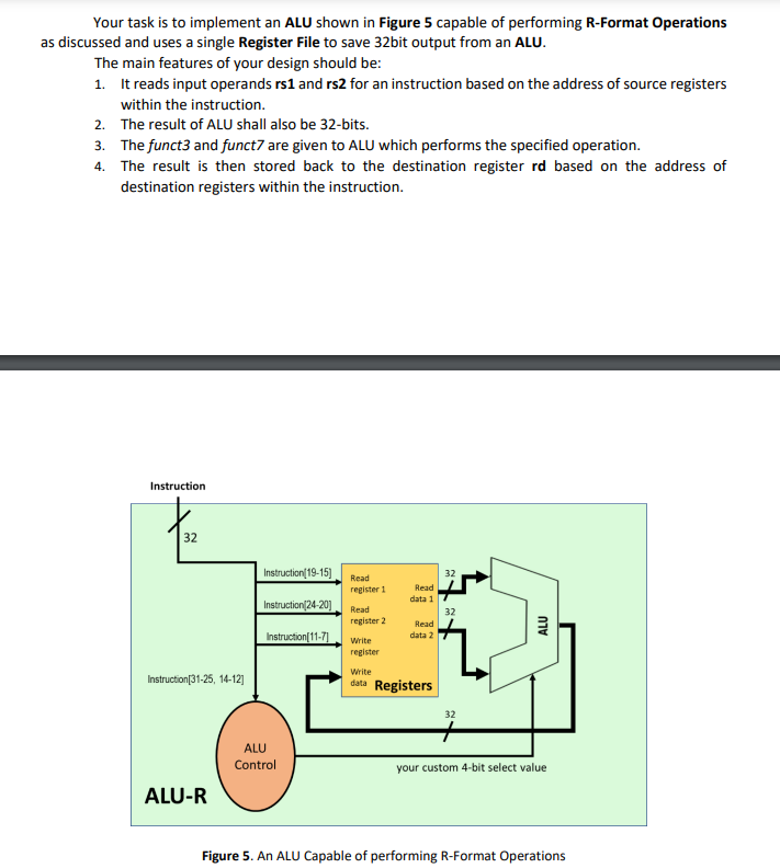
Your task is to implement an ALU shown in Figure capable of performing RFormat Operations
as discussed and uses a single Register File to save bit output from an ALU.
The main features of your design should be:
It reads input operands rs and rs for an instruction based on the address of source registers
within the instruction.
The result of ALU shall also be bits.
The funct and funct are given to ALU which performs the specified operation.
The result is then stored back to the destination register rd based on the address of
destination registers within the instruction.
Figure An ALU Capable of performing RFormat Operations Initializing Register File:
Although it is not a standard way but for this time, in your Registers module, use initial block to initialize
the registers according to the following instructions.
Suppose that the five digits of your roll number are represented in a variable named ROLL.
Like Hazoor's roll no is PHDEE therefore ROLL In your Registers module,
initialize the registers dots, with the values from the following formula:
Example of initializing RAM within your HDL source code: The following example show the initialization
of register contents for your design. For more detailed information please visit and for a useful
discussion is also included at There is an initial block inside your register file which initializes the
contents of with the values from the file register.data. There are values of the register.data file and
all values are of bits. We have used binary data and readmemb function for initializing, you can use
hexadecimal data and readmemh function.
module RegisterFile
inputoutput ports
;
reg : R :; initial begin $readmembregisterdata", R; end
other code goes here endmodule
contents of the file register.data
Question # Marks
Write a testbench to simulate and verify your design. Specifically, you need to test by giving the
sequence of instructions from table and verify the functionality.
Table Set of Instructions for Testbench Code
Note:
Your Report should contain a Verilog Module, b Verilog Testbench, c RTL Schematics, d Resource
Utilization, e Simulation Waveform, f Produced Outputs
Step by Step Solution
There are 3 Steps involved in it
1 Expert Approved Answer
Step: 1 Unlock

Question Has Been Solved by an Expert!
Get step-by-step solutions from verified subject matter experts
Step: 2 Unlock
Step: 3 Unlock