Answered step by step
Verified Expert Solution
Question
1 Approved Answer
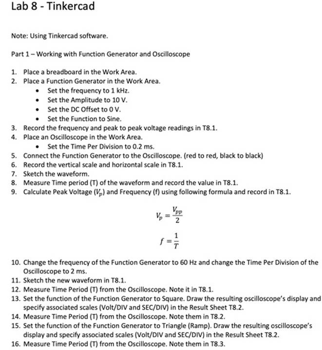
Lab 8 Tinkercad Note: Using Tinkercad software. Part 1 - Working with Function Generator and Oscilloscope 1. Place a breadboard in the Work Area.


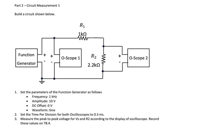
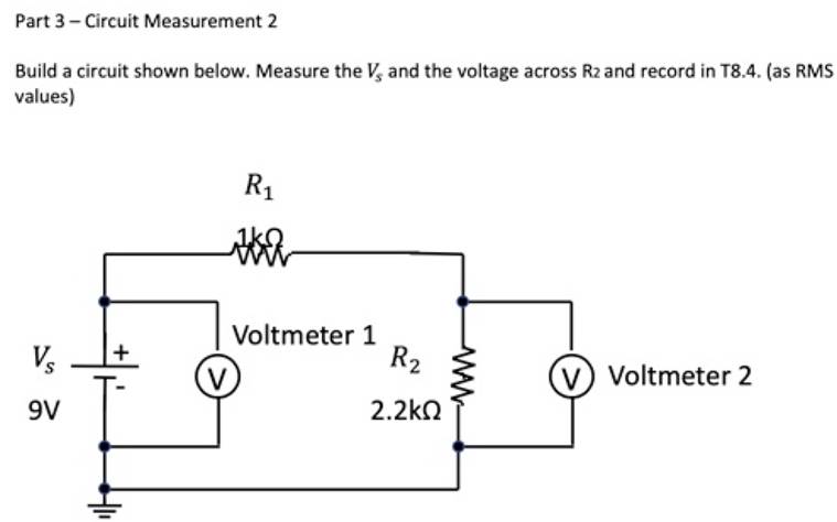
Lab 8 Tinkercad Note: Using Tinkercad software. Part 1 - Working with Function Generator and Oscilloscope 1. Place a breadboard in the Work Area. 2. Place a Function Generator in the Work Area. Set the frequency to 1 kHz. Set the Amplitude to 10 V. Set the DC Offset to 0 V. Set the Function to Sine. 3. Record the frequency and peak to peak voltage readings in T8.1. 4. Place an Oscilloscope in the Work Area. Set the Time Per Division to 0.2 ms. 5. Connect the Function Generator to the Oscilloscope. (red to red, black to black) 6. Record the vertical scale and horizontal scale in T8.1. 7. Sketch the waveform. 8. Measure Time period (T) of the waveform and record the value in T8.1. 9. Calculate Peak Voltage (V) and Frequency (f) using following formula and record in T8.1. || Vpp || 17 10. Change the frequency of the Function Generator to 60 Hz and change the Time Per Division of the Oscilloscope to 2 ms. 11. Sketch the new waveform in T8.1. 12. Measure Time Period (T) from the Oscilloscope. Note it in T8.1. 13. Set the function of the Function Generator to Square. Draw the resulting oscilloscope's display and specify associated scales (Volt/DIV and SEC/DIV) in the Result Sheet T8.2. 14. Measure Time Period (T) from the Oscilloscope. Note them in T8.2. 15. Set the function of the Function Generator to Triangle (Ramp). Draw the resulting oscilloscope's display and specify associated scales (Volt/DIV and SEC/DIV) in the Result Sheet T8.2. 16. Measure Time Period (T) from the Oscilloscope. Note them in T8.3. Part 2 - Circuit Measurement 1 Build a circuit shown below. Function Generator R 1 www O-Scope 1 R2 2.2 www O-Scope 2 1. Set the parameters of the Function Generator as follows Frequency: 1 kHz Amplitude: 10 V DC Offset: 0 V Waveform: Sine 2. Set the Time Per Division for both Oscilloscopes to 0.3 ms. 3. Measure the peak to peak voltage for Vs and R2 according to the display of oscilloscope. Record these values on T8.4. Part 3 - Circuit Measurement 2 Build a circuit shown below. Measure the V, and the voltage across R2 and record in T8.4. (as RMS values) Vs 9V 41 R tha V Voltmeter 1 R 2.2 www (V) Voltmeter 2
Step by Step Solution
★★★★★
3.49 Rating (146 Votes )
There are 3 Steps involved in it
Step: 1
Of course I can assist you with analyzing the information from the Lab 8 Tinkercad instructions and image you provided Analyzing the Lab Instructions ...
Get Instant Access to Expert-Tailored Solutions
See step-by-step solutions with expert insights and AI powered tools for academic success
Step: 2

Step: 3

Ace Your Homework with AI
Get the answers you need in no time with our AI-driven, step-by-step assistance
Get Started


