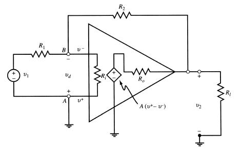
Convert the amplifier circuit of Fig. 5-11 into a noninverting configuration and assume the same conditions as
Question:
Convert the amplifier circuit of Fig. 5-11 into a noninverting configuration and assume the same conditions as specified in Example 5.27 with v1(t) as the input, v2(t) as the output, Ri = ∞, Ro = 0, k = 1 + R2/R1, and the op amp model specified by Example 5.26.
(a) Find the circuit’s input-output relationship in the time domain.
(b) Let v1(t) = V1 cos 2π ft produce an output v2(t) = V2 cos(2π ft − θ). Develop an expression for magnitude gain |V2/V1| vs. frequency.
(c) Verify that the gain-bandwidth product of the noninverting amplifier circuit is the same as that of the op amp’s open-loop, a0 f0.
Data from Figure 5-11

Data from Example 5.27
In the inverting amplifier circuit of Fig. 5-11, v1(t) is the input and v2(t) is the output. Let Ri = ∞, Ro = 0, and assume the 741 op amp model specified by Example 5.26.
At low frequencies the magnitude open-loop gain of a 741 op amp varies as
where typically a0 = 200,000 and f0 = 5 Hz.
Data from Example 5.26
At low frequencies the magnitude open-loop gain of a 741 op amp varies as

where typically a0 = 200,000 and f0 = 5 Hz.
Step by Step Answer:

Schaum S Outline Of Electric Circuits
ISBN: 9781260011968
7th Edition
Authors: Mahmood Nahvi, Joseph Edminister


