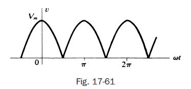
Figure 17-61 shows a full-wave-rectified sine wave representing the voltage applied to the terminals of an LC
Question:
Figure 17-61 shows a full-wave-rectified sine wave representing the voltage applied to the terminals of an LC series circuit. Use the trigonometric Fourier series to find the voltages across the inductor and the capacitor.

Transcribed Image Text:
Vm 0 TT Fig. 17-61 2 ال
Fantastic news! We've Found the answer you've been seeking!
Step by Step Answer:
Answer rating: 66% (3 reviews)

Answered By

Ashington Waweru
I am a lecturer, research writer and also a qualified financial analyst and accountant. I am qualified and articulate in many disciplines including English, Accounting, Finance, Quantitative spreadsheet analysis, Economics, and Statistics. I am an expert with sixteen years of experience in online industry-related work. I have a master's in business administration and a bachelor’s degree in education, accounting, and economics options.
I am a writer and proofreading expert with sixteen years of experience in online writing, proofreading, and text editing. I have vast knowledge and experience in writing techniques and styles such as APA, ASA, MLA, Chicago, Turabian, IEEE, and many others.
I am also an online blogger and research writer with sixteen years of writing and proofreading articles and reports. I have written many scripts and articles for blogs, and I also specialize in search engine
I have sixteen years of experience in Excel data entry, Excel data analysis, R-studio quantitative analysis, SPSS quantitative analysis, research writing, and proofreading articles and reports. I will deliver the highest quality online and offline Excel, R, SPSS, and other spreadsheet solutions within your operational deadlines. I have also compiled many original Excel quantitative and text spreadsheets which solve client’s problems in my research writing career.
I have extensive enterprise resource planning accounting, financial modeling, financial reporting, and company analysis: customer relationship management, enterprise resource planning, financial accounting projects, and corporate finance.
I am articulate in psychology, engineering, nursing, counseling, project management, accounting, finance, quantitative spreadsheet analysis, statistical and economic analysis, among many other industry fields and academic disciplines. I work to solve problems and provide accurate and credible solutions and research reports in all industries in the global economy.
I have taught and conducted masters and Ph.D. thesis research for specialists in Quantitative finance, Financial Accounting, Actuarial science, Macroeconomics, Microeconomics, Risk Management, Managerial Economics, Engineering Economics, Financial economics, Taxation and many other disciplines including water engineering, psychology, e-commerce, mechanical engineering, leadership and many others.
I have developed many courses on online websites like Teachable and Thinkific. I also developed an accounting reporting automation software project for Utafiti sacco located at ILRI Uthiru Kenya when I was working there in year 2001.
I am a mature, self-motivated worker who delivers high-quality, on-time reports which solve client’s problems accurately.
I have written many academic and professional industry research papers and tutored many clients from college to university undergraduate, master's and Ph.D. students, and corporate professionals. I anticipate your hiring me.
I know I will deliver the highest quality work you will find anywhere to award me your project work. Please note that I am looking for a long-term work relationship with you. I look forward to you delivering the best service to you.
3.00+
2+ Reviews
10+ Question Solved
Related Book For 

Schaum S Outline Of Electric Circuits
ISBN: 9781260011968
7th Edition
Authors: Mahmood Nahvi, Joseph Edminister
Question Posted:
Students also viewed these Engineering questions
-
The equivalent-circuit parameters in ohms per phase referred to the stator for a two-phase, 1.0 kW, 220-V, four-pole, 60-Hz, squirrel-cage induction motor are given below. The no-load rotational loss...
-
Find the voltage applied to an X-ray tube with nickel anticathode if the wavelength difference between the Ks line and the short-wave cut-off of the continuous X-ray spectrum is equal to 84 pro.
-
The voltage shown in Figure is produced by applying a sinusoidal voltage to a full wave rectifier. The Fourier series approximation to this function is Suppose this voltage is applied to a series RC...
-
1) The following information relates to the ABCs depreciable assets. Class 1 - During 2020, a new office building was acquired at a total cost of $623,000. Of this total, it is estimated that the...
-
The Coca-Cola Company and PepsiCo, Inc. Instructions Go to the books companion website and use information found there to answer the following questions related to The Coca-Cola Company and PepsiCo,...
-
Figure 25.41 shows a portion of a circuit used to model muscle cells and neurons. All resistors have the same value R = 1.5 M?, and the emfs are ? 1 = 75 mV, ? 2 = 45 mV, and ? 3 = 20 mV. Find the...
-
Why is there sometimes difficulty with the MRP system? LO,1
-
SpringFresh provides commercial laundry and dry cleaning services to local hospitals, hotels, and restaurants. Management believes that the dry cleaning business is a loser, even though dry cleaning...
-
What is the effect of the following transaction on the basic accounting equation? Paid $ 8 0 0 for advertising that ran on the radio. Question 1 2 Select one: a . Assets increase, liabilities...
-
A pure inductance, L = 10 mH, has an applied voltage with the waveform shown in Fig. 17-60, where = 200 rad/s. Obtain the current series in trigonometric form and identify the current waveform. 10 0...
-
A three-element series circuit, with R = 5 , L = 5 mH, and C = 50 F, has an applied voltage u = 150 sin 1000t + 100 sin 2000t + 75 sin 3000t (V). Find the effective current and the average power for...
-
Faune Furniture Co. consists of two divisions, Bedroom Division and Dining Room Division. The results of operations for the most recent quarter are: (a) Determine the company's sales mix. (b)...
-
The financial statements for the Columbia Sportswear Company can be found in Appendix A, and Under Armour, Inc.'s financial statements can be found in Appendix B at the end of this book. Required a....
-
Use the data from SE3-8 to prepare the closing entries for The Decade Company. Close the temporary accounts to income summary. The balance of \(\$ 8,500\) in the retained earnings account is from the...
-
Adjusting Entries The following selected accounts appear in the Birch Company's unadjusted trial balance as of December 31, the end of the fiscal year (all accounts have normal balances): Required...
-
Closing Entries Use the information provided in E3-5A to prepare journal entries to close the accounts using the Income Summary account. After these entries are posted, what is the balance in the...
-
Ceva, Inc. manufactures and services jet engines for air carriers. The engines cost \($10\) to \($40\) million each, depending on the specifications and plane. A 10-year service contract for a single...
-
A planer has a 10-hp motor, and 75% of the motor output is available at the cutting tool. The specific power for cutting cast iron certain metal is 0.03 W/mm3 or .67 hp/in3/min. What is the maximum...
-
A copper wire (density = 8.96 g/cm 3 ) has a diameter of 0.25 mm. If a sample of this copper wire has a mass of 22 g, how long is the wire?
-
The graph shows the position function of a car. Use the shape of the graph to explain your answers to the following questions. (a) What was the initial velocity of the car? (b) Was the car going...
-
Valerie is driving along a highway. Sketch the graph of the position function of her car if she drives in the following manner: At time t = 0, the car is at mile marker 15 and is traveling at a...
-
If a ball is thrown into the air with a velocity of 40 ft/s, its height (in feet) after seconds is given by Y = 40t 16t2. Find the velocity when t = 2.
-
You are evaluating a new project for the firm you work for, a publicly listed firm. The firm typically finances new projects using the same mix of financing as in its capital structure, but this...
-
state, "The subscription price during a rights offering is normally r; lower ; lower r; higher er; higher than the rights-on price and
-
Arnold inc. is considering a proposal to manufacture high end protein bars used as food supplements by body builders. The project requires an upfront investment into equipment of $1.4 million. This...

Study smarter with the SolutionInn App


