In the circuit of Fig. 12-72, with a 0 = 2 105 and 0 =
Question:
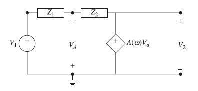
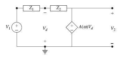
In the circuit of Fig. 12-72,
with a0 = 2 × 10⁵ and ω0 = 10π. Find the frequency response H(ω) =V2/V1 and compare it with the frequency response of the circuit under an ideal op amp assumption (item a) as given in Problem 12-43.

Data from Problem 12-43
In the circuit of Fig. 12-72, assume R = 1 kΩ, C = 100 nF, and A = ∞. For each entry given in the following table, derive and verify the listed H( jω) and the magnitude Bode plot. Show that in all cases the filter is of first-order with ω0 = 1/(RC) = 10000 rad/s.

Step by Step Answer:
Related Book For 

Schaum S Outline Of Electric Circuits
ISBN: 9781260011968
7th Edition
Authors: Mahmood Nahvi, Joseph Edminister
Question Posted:


