

Question: Consider the ECL logic circuit in Figure P17.6. Neglect base currents. (a) Determine the reference voltage (V_{R}). (b) Find the logic 0 and logic 1
Consider the ECL logic circuit in Figure P17.6. Neglect base currents.
(a) Determine the reference voltage \(V_{R}\).
(b) Find the logic 0 and logic 1 voltage values at each output \(v_{O 1}\) and \(v_{O 2}\). Assume that inputs \(v_{X}\) and \(v_{Y}\) have the same values as the logic levels at \(v_{O 1}\) and \(v_{O 2}\).
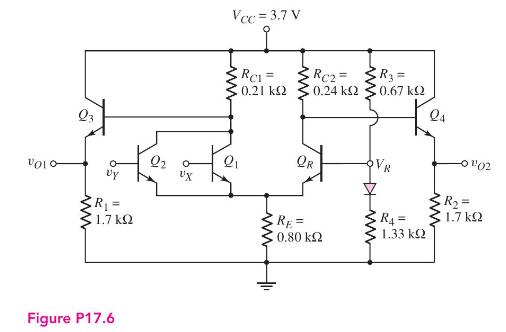
Q3 Vy R = 1.7 kQ Figure P17.6 UX Vcc = 3.7 V ww RC1 = 0.21 www ww RC2= 0.24 QR www R3 = 0.67 24 VR RE= R4= 0.80 1.33 + 1102 R = ww 1.7
Step by Step Solution
There are 3 Steps involved in it
a Reference Voltage VR To find the reference voltage VR we use the voltage divider formula ... View full answer

Get step-by-step solutions from verified subject matter experts