

Question: Consider the transformer-coupled common-emitter circuit shown in Figure P8.33 with parameters (V_{C C}=12 mathrm{~V}, R_{E}=20 Omega, R_{L}=8 Omega, R_{1}=) (2.3 mathrm{k} Omega), and (R_{2}=1.75 mathrm{k}
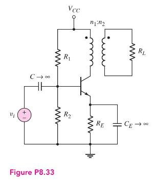
Consider the transformer-coupled common-emitter circuit shown in Figure P8.33 with parameters \(V_{C C}=12 \mathrm{~V}, R_{E}=20 \Omega, R_{L}=8 \Omega, R_{1}=\) \(2.3 \mathrm{k} \Omega\), and \(R_{2}=1.75 \mathrm{k} \Omega\). The transistor parameters are \(\beta=40\) and \(V_{B E}(\) on \()=0.7 \mathrm{~V}\).
(a) Determine the quiescent value \(I_{C Q}\).
(b) Determine the turns ratio \(a\) such that the maximum power is delivered to the load.
(c) Determine the maximum power that can be delivered to the load if the voltage \(v_{1}\) is to remain in the range \(2 \leq v_{1} \leq 20 \mathrm{~V}\).
(d) Using the results of part (c) and neglecting currents in the bias resistors, find the conversion efficiency.
Vi Vcc 2 www C R www +1 R Figure P8.33 RL RE CE
Step by Step Solution
3.43 Rating (162 Votes )
There are 3 Steps involved in it

Get step-by-step solutions from verified subject matter experts