

292 Transistor Biasing The circuit shown in Figure P292 is a typical biasing arrangement for a BJT-type
Question:
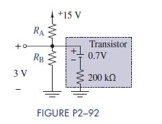
2–92 Transistor Biasing The circuit shown in Figure P2−92 is a typical biasing arrangement for a BJT-type transistor. The actual transistor for this problem can be modeled as 0:7-V battery in series with a 200-kΩ resistor. Biasing allows signals that have both positive and negative variations to be properly amplified by the transistor.
Select the two biasing resistors RA and RB so that 3 0:1V appears across RB.
Fantastic news! We've Found the answer you've been seeking!
Step by Step Answer:

Answered By
Evans Cherono
I am an Information Technology Graduate and willing to work on any computer science or IT work to ensure I do my best all the time.
2+ Reviews
10+ Question Solved
Related Book For 
The Analysis And Design Of Linear Circuits
ISBN: 9781119235385
8th Edition
Authors: Roland E. Thomas, Albert J. Rosa, Gregory J. Toussaint
Question Posted:
