

297 Programmable Voltage Divider Figure P297 shows a programmable voltage divider in which digital inputs b0 and
Question:
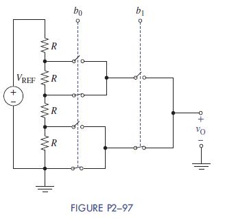
2–97 Programmable Voltage Divider Figure P2−97 shows a programmable voltage divider in which digital inputs b0 and b1 control complementary analog switches connecting a multitap voltage divider to the analog output vO.
The switch positions in the figure apply when digital inputs are low. When inputs go high the switch positions reverse. Find the analog output voltage for (b1,b0) = (0,0), (0,1), (1,0), and
(1,1) when VREF = 12 V.
Fantastic news! We've Found the answer you've been seeking!
Step by Step Answer:

Answered By
BRIAN MUSINGA
I possess a Bachelors of Commerce degree(Marketing option) and am currently undertaking an MBA in marketing. I believe that I possess the required knowledge and skills to tutor in the subject named. I have also written numerous research academic papers much to the satisfaction of clients and my professors.
2+ Reviews
17+ Question Solved
Related Book For 
The Analysis And Design Of Linear Circuits
ISBN: 9781119235385
8th Edition
Authors: Roland E. Thomas, Albert J. Rosa, Gregory J. Toussaint
Question Posted:
