

310 (a) Formulate node-voltage equations for the bridge circuit in Figure P310. (b) Solve for vx and
Question:
3–10
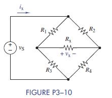
(a) Formulate node-voltage equations for the bridge circuit in Figure P3−10.
(b) Solve for vx and ix when R1 =R4 =1 kΩ,R2 =R3 = 1:5 kΩ, Rx = 680 Ω, and vS =12V.
(c) Repeat
(b) when R4 is a variable resistor that varies from 10 Ω to 10 kΩ.At what value of R4 is the voltage across Rx = 0 V? Use Multisim to find the value by either varying R4 by trial and error to approach the answer, or using a
“Parameter sweep” found under Analyses. To use the latter, proceed as follows: Under “Parameter sweep” select
“Device type:” Resistor; “Name:” your name for our R4;
“Parameter (what you wish to vary):” resistance; “Present value:” Any value within your range—say, 1 kΩ. Under
“Points to sweep,” choose “Linear” sweep variation type.
“Start” at 10 Ω; “Stop” at 10 kΩ. Use 100 points—Multisim automatically calculates the increment. Under “More Options” choose “DCOperating Point.” Then go to the output tab under the Parameter Sweep window. Since you want the voltage across the 680-Ω resistor, create an expression for it, such as Vð2Þ—Vð3Þ if those are the node names of the two nodes determining the voltage. Choose “Simulate.” Grapher View will plot a graph of the resistance value versus the voltage across the 680-Ω resistor. Make sure the grid lines are shown on your graph. Use the cursor to find the value of resistance that causes the voltage to go to zero.
Step by Step Answer:

This question has not been answered yet.
You can Ask your question!

The Analysis And Design Of Linear Circuits
ISBN: 9781119235385
8th Edition
Authors: Roland E. Thomas, Albert J. Rosa, Gregory J. Toussaint
