

A 50-mF capacitor and a 100-mH inductor are connected in parallel with a closed switch as shown
Question:
A 50-mF capacitor and a 100-mH inductor are connected in parallel with a closed switch as shown in Figure P6–17. The inductor has 25 mA flowing through it at t ¼ 0. The switch opens at t ¼ 0.
(a) Find the initial voltage across the capacitor at t ¼ 0.
(b) Write an equation for the voltage across the elements for t > 0. Do not solve it.
(c) Simulate the circuit using OrCAD. Connect an inductor in parallel with a capacitor and assign the appropriate initial conditions and run a transient analysis. Plot the voltage across the elements for at least 20 ms.
(d) Characterize the response signal.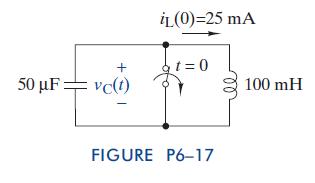
Step by Step Answer:

This question has not been answered yet.
You can Ask your question!
Related Book For 

The Analysis And Design Of Linear Circuits
ISBN: 9781118214299
7th Edition
Authors: Roland E Thomas, Albert J Rosa, Gregory J Toussaint
Question Posted:
