

Analysis ofredundant circuits 1. Analyze the gate circuit of Figure 14.28-a in order to determine the redundancies;
Question:
Analysis ofredundant circuits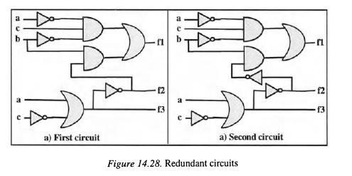
1. Analyze the gate circuit of Figure 14.28-a in order to determine the redundancies; suppress these redundancies and propose a 'clean' circuit completely testable.
2. Analyze the circuit of Figure 14.28-b and compare it to the previous one.
Analyze its testability.
Exereise 14.3. Anti-gliteh eireuit The circuit of Figure 14.29 uses a gate (denoted A) to elirninate the glitches occurring when the input b switches. Unfortunately all stuck-at faults cannot be tested.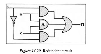
1. Study the circuit to determine this untestable redundancy.
2. Add a testing input T and modify the structure to make it entirely testable.
Exereise 14.4. Easily testable gate network Logical networks (wired or programmable) constitute very used logical implementation means. Fundamentally they comprise a layer of AND cells which receive primary inputs and their complements, and a layer of OR cells delivering the outputs.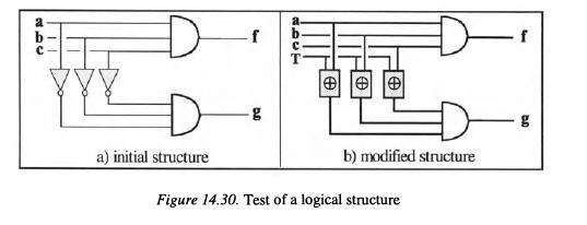
Here we are interested in the test of a network of AND gates with a very simple circuit of 3 inputs
(a,
b, c) and 2 outputs lf and g) drawn in Figure 14.30-a. To facilitate the test, we replace the 3 input inverters by 3 XOR gates controlled by a test input noted T: if T has the value '0', then the signals
a, b and c are complemented, and if T = '1' they are transmitted without complementation (see Figure 14.30-b).
How can this modification improve the test?
Step by Step Answer:


Design Of Dependable Computing Systems
ISBN: 978-9048159413
1st Edition
Authors: J C Geffroy ,G Motet
