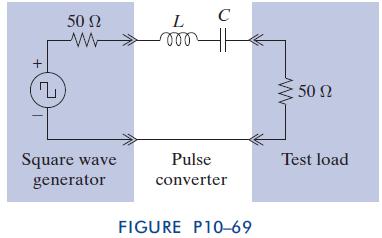
Pulse Conversion Circuit The purpose of the test setup in Figure P1069 is to deliver damped sine
Question:
Pulse Conversion Circuit The purpose of the test setup in Figure P10–69 is to deliver damped sine pulses to the test load. The excitation comes from a 1-Hz square wave generator. The pulse conversion circuit must deliver damped sine waveforms with z 10 krad/s to 50-V and 600-V loads. The recommended values for the pulse conversion circuit areL¼10mHandC¼
0.1 mF. Verify that the test setup meets the specifications.
(Hint: Compute the voltage across the load for an input signal equal to a unit step function, u(t), and then again for a negative unit step function, u(t).) Note that the output of a square wave generator is the sum of a series of step functions.
Step by Step Answer:

The Analysis And Design Of Linear Circuits
ISBN: 9781118214299
7th Edition
Authors: Roland E Thomas, Albert J Rosa, Gregory J Toussaint


