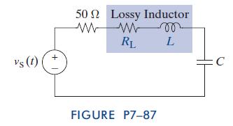
RLCCircuit Design Losses in real inductors can be modeled by a series resistor as shown in Figure
Question:
RLCCircuit Design Losses in real inductors can be modeled by a series resistor as shown in Figure P7–87. In this problem, we include the effect of this resistor on the design of the series RLC circuit shown in the figure. The design requirements include a source resistance of 50V, an undamped natural frequency of 50 kHz, and a damping ratio less than 0.1.
The characteristics of the available inductors are listed below.
L(MH) R1(V) L(MH) R1(V.)
10.0 651 4.7 240 7.5 471 3.9 190 6.8 356 3.3 161 Which inductor would you use in your design and why?
Fantastic news! We've Found the answer you've been seeking!
Step by Step Answer:
Related Book For 

The Analysis And Design Of Linear Circuits
ISBN: 9781118214299
7th Edition
Authors: Roland E Thomas, Albert J Rosa, Gregory J Toussaint
Question Posted:


