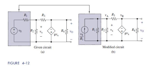
The circuit in Figure 412 (a) is a model of an inverting OP AMP circuit. (a) Use
Question:
The circuit in Figure 4–12
(a) is a model of an inverting OP AMP circuit.
(a) Use node-voltage analysis to find the output υO in terms of the input υS.
(b) Evaluate the input-output relationship found in part
(a) as the gain μ becomes very large.
(c) Assume R1 =R2 = 100 Ω, μ = 1000, and R4 =1 kΩ. Use Multisim to show the effect of the feedback resistor R3 by plotting the output gain K = υO=υS for R3 varying from 10 Ω to 100MΩ.

Fantastic news! We've Found the answer you've been seeking!
Step by Step Answer:
Related Book For 

The Analysis And Design Of Linear Circuits
ISBN: 9781119235385
8th Edition
Authors: Roland E. Thomas, Albert J. Rosa, Gregory J. Toussaint
Question Posted:


