

The circuit in Figure P1138 is in the steady state with i1(t) 5 cos 1000t mA,
Question:
The circuit in Figure P11–38 is in the steady state with i1(t) ¼ 5 cos 1000t mA, R ¼ 1 kV, L, ¼ 2H, and C ¼ 0.5 mF.
(a) Find i2SS(t).
(b) Verify your results using OrCAD. Use IAC for a source and note that the current comes out of the negative terminal
(passive sign convention.). The IPRINTelement on the right side of the figure is an ammeter and it comes from the Special Library. It has a polarity as indicated by the small’’–’’ on the element. You should ensure that it will read the correct current direction. Before you can use the IPRINT element, it needs to be set up to display the current magnitude and phase. Double click on the element and in its property editor place a ‘‘y’’ inAC,MAG, and PHASE boxes. Click the Apply button and close the property editor. To obtain the simulation select AC Sweep/Noise. Set the start frequency and the stop frequency at 159.15 Hz (1000 rad/s). Place a 1 in Points/
Decade. Run the simulation. Under View, select Output File.
Scroll down until you see the IPRINT output.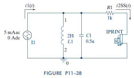
Step by Step Answer:


The Analysis And Design Of Linear Circuits
ISBN: 9781118214299
7th Edition
Authors: Roland E Thomas, Albert J Rosa, Gregory J Toussaint
