

The circuit in Figure P1224 produces a bandstop response for a suitable choice of element values. (a)
Question:
The circuit in Figure P12–24 produces a bandstop response for a suitable choice of element values.
(a) Find the circuit’s transfer function.
(b) Identify the elements that control the two cutoff frequencies.
Select the element values so that the cutoff frequencies are 200 krad/s and 4000 krad/s. Use practical element values with Rs 10 kV and Cs 1mF. Design your passband gain to be þ20 dB.
(c) Use MATLAB to plot the Bode magnitude plot for the values you selected.
(d) Simulate your circuit using OrCAD and compare the results to the MATLAB output.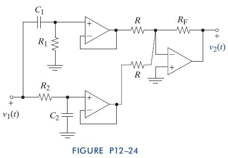
Step by Step Answer:

This question has not been answered yet.
You can Ask your question!
Related Book For 
The Analysis And Design Of Linear Circuits
ISBN: 9781118214299
7th Edition
Authors: Roland E Thomas, Albert J Rosa, Gregory J Toussaint
Question Posted:
