

The circuit in Figure P715 is in the zero state when the input vS(t)20 u(t) is applied.
Question:
The circuit in Figure P7–15 is in the zero state when the input vS(t)¼20 u(t) is applied. IfL¼100mHandR¼1kV, findvO(t)
for t 0. Identify the forced and natural components in the output. On a single set of axes, useMATLAB to plot the forced response, the natural response, and the complete response.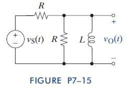
Step by Step Answer:

This question has not been answered yet.
You can Ask your question!
Related Book For 
The Analysis And Design Of Linear Circuits
ISBN: 9781118214299
7th Edition
Authors: Roland E Thomas, Albert J Rosa, Gregory J Toussaint
Question Posted:
